Clamping mechanism and turning machine tool

A clamping mechanism and clamping tooling technology, applied in the direction of clamping, metal processing machinery parts, supports, etc., can solve the problems of deformation and positioning efficiency of thin-walled workpieces, achieve rapid positioning, improve positioning efficiency, and prevent deformation

Pending Publication Date: 2017-09-08
SEKSUN TECH SUZHOU
View PDF7 Cites 3 Cited by
  • Summary
  • Abstract
  • Description
  • Claims
  • Application Information

AI Technical Summary

Problems solved by technology

[0006] The purpose of the present invention is to provide a clamping mechanism to alleviate the technical problems that

Method used


Image

  • Clamping mechanism and turning machine tool
  • Clamping mechanism and turning machine tool
  • Clamping mechanism and turning machine tool

Examples


Embodiment 1

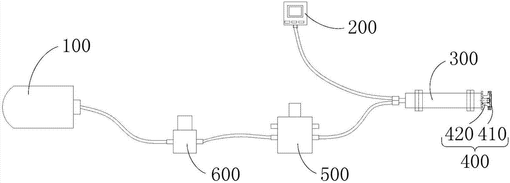
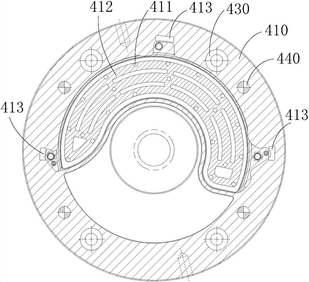
[0032] figure 1 A schematic structural diagram of a clamping mechanism is provided for an embodiment of the present invention, such as figure 1 As shown, the clamping mechanism provided by the embodiment of the present invention includes: a vacuum pump 100, a first vacuum gauge 200, a main shaft 300 and a clamping assembly 400, the vacuum pump 100 and the first vacuum gauge 200 are connected to the main shaft 300, the main shaft 300 is connected to the clamping The components 400 are connected; the clamping component 400 includes a clamping tool 410 , the clamping tool 410 is provided with a positioning surface, and a plurality of vacuum holes 411 are arranged on the positioning surface, and the plurality of vacuum holes 411 communicate with the inside of the main shaft 300 .

[0033] like figure 1 As shown, the main shaft 300 is a hollow tube, one end of the main shaft 300 is connected to the vacuum pump 100 through a vent pipe, and the other end is connected to the clamping...

Embodiment 2

[0056] The purpose of the second embodiment is to provide a turning machine tool to alleviate the technical problems in the prior art that the clamping mechanism may deform the thin-walled workpiece and the positioning efficiency is low.

[0057] The turning machine tool provided in the second embodiment includes the clamping mechanism provided in the first embodiment.

[0058] The turning machine tool provided in Embodiment 2 has the same advantages as the clamping mechanism provided in Embodiment 1 over the prior art, and will not be repeated here.


PUM


Abstract

The invention provides a clamping mechanism and a turning machine tool, and relates to the technical field of machining equipment. The clamping mechanism provided by the invention comprises a vacuum pump, a first vacuum gauge, a main shaft and a clamping assembly, wherein the vacuum pump and the first vacuum gauge are both connected with the main shaft, and the main shaft is connected with the clamping assembly; and the clamping assembly comprises a clamping fixture, a location surface is formed on the clamping fixture, a plurality of vacuum holes are formed in the location surface, and the plurality of vacuum holes all communicate with the interior of the main shaft. The clamping mechanism provided by the invention is applied to a process of clamping a workpiece to alleviate the technical problems of deformation of the thin-walled workpiece and low location efficiency, which are possibly caused by a clamping mechanism in the prior art.

Description

technical field [0001] The invention relates to the technical field of machining equipment, in particular to a clamping mechanism and a turning machine tool. Background technique [0002] The clamping mechanism is a device used to fix the processing object in the process of mechanical manufacturing so that it occupies the correct position for construction or inspection. During turning, according to the content of turning and the shape and size of the workpiece, a three-jaw chuck or a four-jaw chuck is often used to clamp the workpiece. [0003] The three-jaw automatic chuck mainly includes a chuck body, a small bevel gear on the chuck body, a large bevel gear meshing with the small bevel gear, and three claws on the large bevel gear. When the chuck wrench is inserted into the chuck When any small bevel gear on the disc rotates in the square hole, the small bevel gear drives the large bevel gear to rotate, and the plane thread on the back of the large bevel gear drives the t...

Claims


Application Information

Patent Timeline
IPC IPC(8): B23Q3/08B23Q17/00
CPCB23Q3/088B23Q17/005
Inventor 刘汝胜
Owner SEKSUN TECH SUZHOU
Why Eureka
Try Eureka