
Evaporation crucible and evaporation device

A crucible and evaporation technology is applied in the field of display device production, which can solve the problems affecting device performance, denaturation, low thermal conductivity, etc., and achieve the effects of improving heating uniformity, evaporation rate uniformity, and film layer distribution uniformity.

Active Publication Date: 2020-03-13
BOE TECH GRP CO LTD
View PDF4 Cites 0 Cited by
  • Summary
  • Abstract
  • Description
  • Claims
  • Application Information

AI Technical Summary

Problems solved by technology

[0002] Vacuum evaporation method is the key technology for preparing organic light-emitting display devices (Organic Light-Emitting Diode, OLED). The evaporation process often uses a crucible to heat the evaporated material to evaporate it. However, due to the thermal conductivity of the evaporated material Therefore, the temperature of the material to be evaporated near the side wall of the crucible tends to rise faster, while the material to be evaporated farther away from the side wall is heated slowly, so that the evaporation rate of the material near the side wall of the crucible is greater than that of the center of the crucible. The evaporation rate of the material is reduced, forming a sand pile structure, which leads to the collapse of the evaporated material accumulated in the crucible, causing a significant change in the evaporation rate
In order to increase the evaporation rate in the central area, it is necessary to increase the heating temperature, which will easily cause the material near the side wall to be overheated and denatured, resulting in material waste and affecting device performance.

Method used


Image

  • Evaporation crucible and evaporation device
  • Evaporation crucible and evaporation device
  • Evaporation crucible and evaporation device

Examples


Embodiment approach

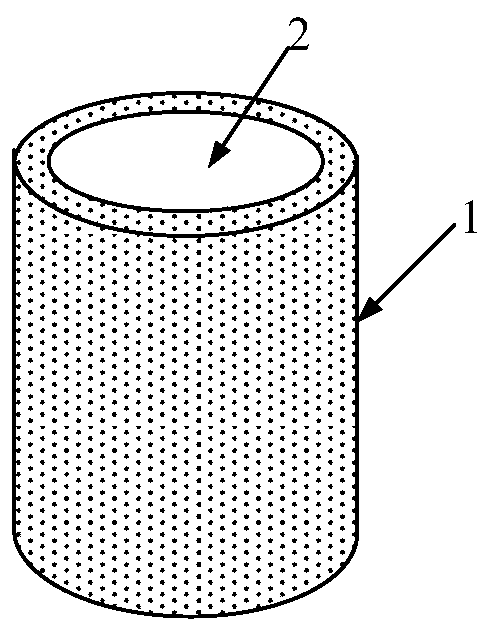
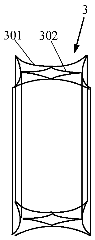
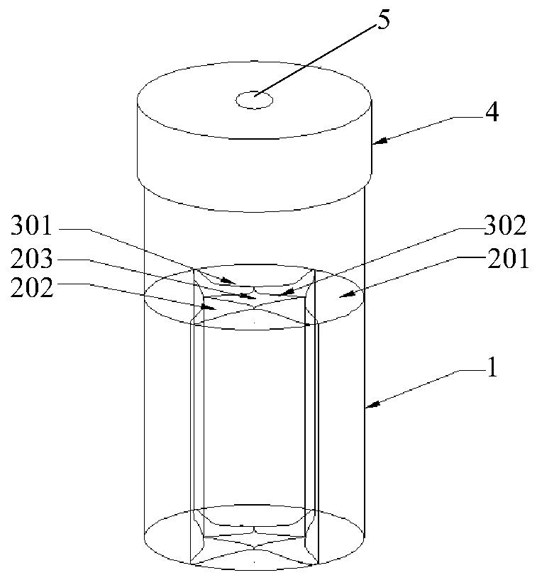
[0028] As the first specific embodiment of the present invention, the structure of the heat conduction structure 3 refers to Figure 2 to Figure 4 As shown in , when the heat conduction structure 3 is arranged in the housing cavity 2, the housing cavity 2 can be divided into a plurality of housing sub-cavities, wherein the axis of the housing cavity 2 passes through one of the housing sub-cavities 203, and the remaining multiple housing sub-cavities 201 and 202 are arranged around the axis of the containing cavity 2, and the opening of each containing sub-cavity 201, 202 and 203 is located at its top. Moreover, the heat conduction spacers 301 and 302 are mesh heat conduction layers, so that the accommodation sub-cavities 201, 202 and 203 can communicate with each other, so that the material to be evaporated can communicate with each other between the accommodation sub-cavities 201, 202 and 203 flow. In the present invention, the accommodating chamber 2 is a cylindrical space,...


PUM


Abstract

The invention provides a vapor plating crucible. The crucible comprises a body, an accommodating chamber is formed in the crucible body, a heat conduction structure is arranged in the accommodating chamber, the heat conduction structure comprises several heat conduction spacing bodies, several heat conduction spacing bodies are used for dividing the accommodating chamber into several subsidiary accommodating chambers with openings, and the accommodating subsidiary chambers are mutually communicated. Correspondingly, the invention also provides a vapor plating apparatus.

Description

technical field [0001] The invention relates to the field of manufacturing display devices, in particular to an evaporation crucible and an evaporation device. Background technique [0002] Vacuum evaporation method is the key technology for preparing organic light-emitting display devices (Organic Light-Emitting Diode, OLED). The evaporation process often uses a crucible to heat the evaporated material to evaporate it. However, due to the thermal conductivity of the evaporated material Therefore, the temperature of the material to be evaporated near the side wall of the crucible tends to rise faster, while the material to be evaporated farther away from the side wall is heated slowly, so that the evaporation rate of the material near the side wall of the crucible is greater than that of the center of the crucible. The evaporation rate of the material is reduced, forming a sand pile structure, which in turn leads to the collapse of the evaporated material accumulated in the ...

Claims


Application Information

Patent Timeline
Patent Type & Authority Patents(China)
IPC IPC(8): C23C14/24
CPCC23C14/243
Inventor 刘暾刘晓云
Owner BOE TECH GRP CO LTD
Learn More