Antenna switch device and terminal

An antenna switch and antenna technology, applied in electrical components, diodes, transmission systems, etc., can solve the problems of shortened communication distance of terminals, inability to match and replace, and influence on antenna performance, and achieve flexible circuit design structure, guarantee flexibility, The effect of improving performance

Active Publication Date: 2017-09-08
上海东洲罗顿通信股份有限公司
View PDF5 Cites 0 Cited by
  • Summary
  • Abstract
  • Description
  • Claims
  • Application Information

AI Technical Summary

Problems solved by technology

[0003] In the process of realizing the present invention, the inventor found that: in the prior art, the terminal antenna switch mostly adopts a specially designed integrated switch with multiple ports, and the multiple ports correspond to different channels to realize the function of multi-channel switch, but , the multi-port integrated switch has low flexibility and cannot be matched and replaced according to the number of switch channels required by the antenna. It will also cause waste when the antenna does not use so many ports.
In some specially designed antenna switching circuits, when the switching element is in the cut-off state, the equivalent capacitance of the switching element cut-off and the matching circuit will form a resonance, which will affect the performance of the antenna, and then shorten the communication distance of the terminal and the transmission rate. Low, poor call quality, etc.

Method used


Image

  • Antenna switch device and terminal
  • Antenna switch device and terminal
  • Antenna switch device and terminal

Examples


Embodiment Construction

[0031] In order to make the purpose, technical solutions and advantages of the embodiments of the present invention more clear, various implementation modes of the present invention will be described in detail below in conjunction with the accompanying drawings. However, those of ordinary skill in the art can understand that, in each implementation manner of the present invention, many technical details are provided for readers to better understand the present application. However, even without these technical details and various changes and modifications based on the following implementation modes, the technical solution claimed in this application can also be realized.

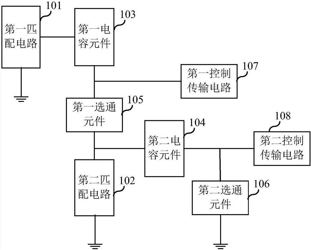
[0032] The first embodiment of the present invention relates to an antenna switch device, including at least one switch circuit, such as figure 1 As shown, it includes a first matching circuit 101, a second matching circuit 102, a first capacitive element 103, a second capacitive element 104, a first gating el...


PUM


Abstract

The embodiment of the invention relates to the field of wireless communication technology, and discloses an antenna switch device and a terminal thereof. The antenna switch device comprises at least one switch circuit, the switch circuit comprises: a first matching circuit, a second matching circuit, a first capacitor element, a second capacitor element, a first gating element, a second gating element, a first control transmission circuit and a second control transmission circuit, wherein when a first end of the first control transmission circuit receives a first control signal, the first gating element is in a turn-on state under the control of the first control signal, and when the first end of the second control transmission circuit receives a second control signal, the second gating element is in a disconnected state according to the second control signal. In the antenna switch device disclosed by the invention, the flexibility of the antenna switch circuit of the terminal is improved, and meanwhile better performance of the antenna switch is guaranteed.

Description

technical field [0001] Embodiments of the present invention relate to the technical field of wireless communication, and in particular to an antenna switch device and a terminal. Background technique [0002] In wireless communication, the antenna switch is a switch to switch the working state of the antenna, connected between the wire and the RF processing circuit, the switching of the antenna switch is controlled by the CPU (Central Processing Unit, Central Processing Unit), the function of the antenna switch is to increase Antenna operating bandwidth. In the terminal design, since the antenna switch is a radio frequency front-end device, it directly affects the sending and receiving capability of mobile phone signals and the appearance of the whole machine. In addition, it needs to be compatible with multiple working modes at the same time, covering more than 40 communication frequency bands, so the terminal antenna switch circuit The design of the terminal is a key link...

Claims


Application Information

Patent Timeline
Patent Type & Authority Applications(China)
IPC IPC(8): H04B1/00H04B1/401H03K17/74
CPCH03K17/74H04B1/006H04B1/401
Inventor 邵一祥胡魏魏
Owner 上海东洲罗顿通信股份有限公司
Why Eureka
Try Eureka