
Geotechnical centrifuge model testing equipment and excavation simulation method

A technology of model testing and geotechnical centrifugation, which is applied in basic structure testing, basic structure engineering, construction, etc., can solve problems such as unfavorable safe operation of centrifuges, difficulty in reflecting real working conditions, and complicated excavation soil operations, etc., to achieve convenience Effective simulation, convenient model making, and the effect of ensuring accuracy

Active Publication Date: 2017-09-12
CHINA UNIV OF GEOSCIENCES (WUHAN) +1
View PDF5 Cites 8 Cited by
  • Summary
  • Abstract
  • Description
  • Claims
  • Application Information

AI Technical Summary

Problems solved by technology

When using the centrifugal model to simulate the excavation of the foundation pit, it is difficult to reflect the real working conditions by shutting down and then excavating. It is complicated to use the hydraulic device to lift the excavated soil. At the same time, the hydraulic device is often heavy, and the increase of the counterweight on the model side is not conducive to the centrifuge. safe operation

Method used


Image

  • Geotechnical centrifuge model testing equipment and excavation simulation method

Examples


Embodiment 1

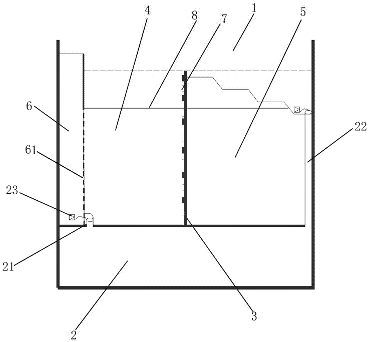
[0028] A kind of geotechnical centrifugal model test equipment, including a model box 1, the bottom of the model box is provided with a water storage tank 2, and the middle and upper part is located on the water storage tank to separate the foundation pit cavity 5 and fill with The soil filling cavity 4 of the soil material is provided with a water level water tank 6 connected to the water storage tank through a conduit 21 to control the water level of the filling cavity. The gaps are connected through dense seepage holes 61, and the foundation pit cavity is connected to the water storage tank through a conduit 22. The strain gauge of the internal force that the plate bears and the earth pressure sensor 7 of the change of lateral earth pressure.

[0029] The foundation pit cavity and the filling cavity are arranged adjacently, and the water level water tank is arranged on the wall of the water storage tank on the side of the filling cavity facing away from the foundation cavit...

Embodiment 2

[0043] The difference from the above-mentioned embodiment is that the filling cavity is set outside the foundation pit cavity, and the water level water tank is set against the outer wall of the filling cavity or inserted in the filling cavity, and inserted in the filling cavity. Water seepage holes are arranged on the wall circumference of the water level water tank in the soil cavity.

Embodiment 3

[0045] The difference from the above embodiment is that the water storage tank includes two chambers respectively connected to the water level water tank and the foundation pit cavity, and the conduit 1 and conduit 2 are each connected with a suction pump. When the liquid suction pump is set on the conduit one and the conduit two, the filling liquid in the step one and the water level water tank injection in the step three can be pumped from the two chambers to the excavation area and the water level water tank respectively by the liquid suction pump. Thus, the setting of the liquid supply system can be omitted. The two chambers of the liquid storage tank respectively store water and liquids with a density similar to that of the soil, and are recyclable and recycled for many times. Repeated tests are also carried out continuously to obtain multiple sets of data, and the experimental results are more accurate.

[0046] Compared with the existing simulation technology of foundat...


PUM


Abstract

The invention belongs to the field of centrifugal model tests, and particularly relates to geotechnical centrifuge model testing equipment and an excavation simulation method. The geotechnical centrifuge model testing equipment comprises a model box. A water storage tank is arranged at the inner bottom of the model box. A foundation pit cavity and an earth filling cavity filled with an earth material are formed in the upper middle portion of the model box and located on the water storage tank, and the foundation pit cavity and the earth filling cavity are divided by a vertically-arranged underground diaphragm wallboard. A water level tank which is connected with the water storage tank through a first guide pipe and used for controlling the water level of the earth filling cavity to go up and down is arranged in the earth filling cavity. The water level tank and the earth filling cavity communicate with each other through densely-distributed water seepage holes. The foundation pit cavity is connected with the water storage tank through a second guide pipe. The underground diaphragm wallboard is provided with a strain gage used for monitoring inner force exerted on the underground diaphragm wallboard due to foundation pit excavation and underground water level change, and an earth pressure sensor used for monitoring lateral soil pressure change. The testing method for simulating water level rising and falling and foundation pit excavation under the condition that a geotechnical centrifugal machine is not halted is adopted; and test operability is high, the model can be manufactured conveniently, soil mass water level change of the periphery of a field foundation pit and the excavation process of the foundation pit can be truly simulated, and a powerful approach is provided for studying stability of the foundation pit wall.

Description

technical field [0001] The invention belongs to the field of centrifugal model tests, and in particular relates to a geotechnical centrifugal model test device and an excavation simulation method. Background technique [0002] In the stratum with strong water permeability, the seepage stability of foundation pit is one of the important factors to ensure the safety of foundation pit. At present, the research on the seepage of foundation pits mainly focuses on the local area around the foundation pit, and less consideration is given to the influence of factors such as changes in the water level of adjacent rivers and rainstorm infiltration during excavation of foundation pits on the seepage stability of foundation pits. The city located in the first-level terrace of the Yangtze River, due to the engineering geological characteristics of the first-level terrace, and the rise and fall of the groundwater level around the foundation pit in actual engineering, it is very easy to ca...

Claims


Application Information

Patent Timeline
IPC IPC(8): E02D33/00
CPCE02D33/00E02D2600/10
Inventor 胡勇李云安李波李从安杜永奎
Owner CHINA UNIV OF GEOSCIENCES (WUHAN)
Learn More