
a grain dryer

A grain dryer and drying machine technology, applied in the direction of dryer, drying, grain drying, etc., can solve the constraints that are easily affected by weather and site, natural drying cannot meet the demand, and grain drying is uneven Incomplete and other problems, to achieve the effect of preventing secondary drying, high work efficiency, and good quality of materials

Inactive Publication Date: 2019-03-12
唐山久发农业科技有限公司
View PDF5 Cites 0 Cited by
  • Summary
  • Abstract
  • Description
  • Claims
  • Application Information

AI Technical Summary

Problems solved by technology

my country's grains are harvested 1 to 3 times a year and need to be stored for several years. However, in the process of grain production and grain drying, natural drying is easily restricted by the influence of weather and venues.
With the large-scale promotion and application of grain harvesters and the rise of large grain growers, natural drying can no longer meet the demand, and grain drying equipment must be used
[0003] Most of the current drying equipment is to put the grain into the drying equipment and take out the grain after a certain period of time, but the moisture content of each grain is different, which will make some grains have low moisture content and some grains. High, resulting in uneven and incomplete drying of grain

Method used


Image

  • a grain dryer
  • a grain dryer
  • a grain dryer

Examples


Embodiment Construction

[0022] The embodiment given below intends to further illustrate the present invention, but can not be interpreted as the restriction to protection scope of the present invention, those skilled in the art still belongs to the protection of the present invention to some non-essential improvements and adjustments of the present invention according to the content of the present invention scope.

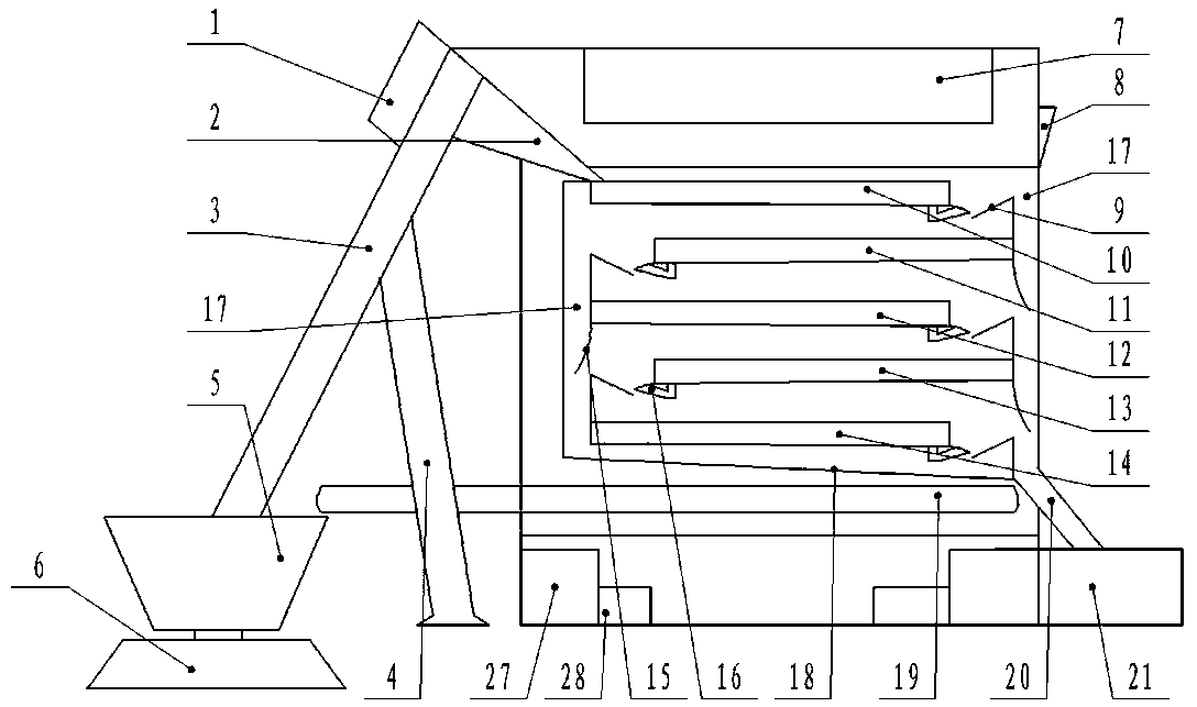
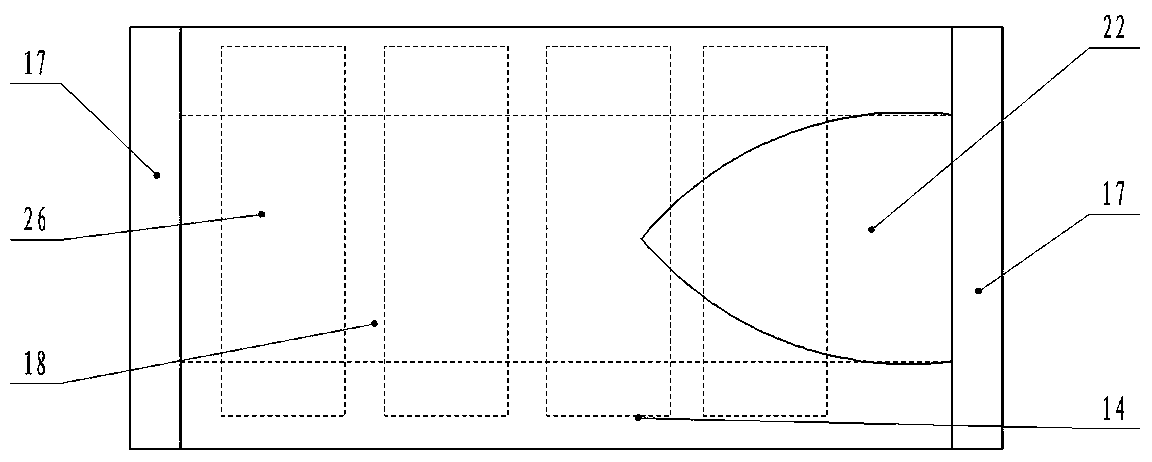
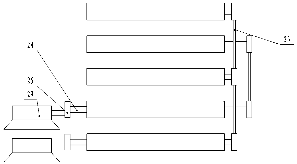
[0023] exist figure 1 , 2 , 3, 1. Feeding machine motor, 2. Feeding port, 3. Feeding machine, 4. Feeding machine bracket, 5. Grain storage bin, 6. Base, 7. Dehumidifier, 8. Exhaust valve , 9. Blocking plate, 10. The first drying plate, 11. The second drying plate, 12. The third drying plate, 13. The fourth drying plate, 14. The fifth drying plate, 15. Arc Shaped baffle plate, 16. Fan, 17. Dry material feeding bin 1, 18, Dry material feeding bin 2, 19. Conveyor belt, 20. Outlet, 21. Collecting bin, 22. Splitter plate, 23. Connecting rod, 24. connecting shaft, 25. eccentric wheel, 26. sl...


PUM


Abstract

The invention provides a grain drying machine. The grain drying machine comprises a drying machine body, a feeding machine, a dehumidification machine, drying plates, a conveyor belt, dry material moving bins and air heaters. The grain drying machine is characterized in that a feeding inlet is formed in one side of the upper end of the drying machine body and connected with the feeding machine. The lower end of the feeding machine is arranged inside a grain storage bin. An exhaust valve is arranged on the other side of the upper end of the drying machine body. The dehumidification machine is arranged in the middle of the upper end of the drying machine body. The air heaters are arranged on the two sides of the lower end of the drying machine body. More than three stacking type drying plates are arranged inside the drying machine body, and every two adjacent drying plates are arranged in a staggered mode. The first dry material moving bins are arranged on the two sides of the interior of the drying machine body, the conveyor belt is arranged at the lower end of the second dry material moving bin, the first dry material moving bins are connected with a discharging outlet, and the discharging outlet is connected with a material collecting box. The grain drying machine has the advantages of being simple in structure, high in practicability and efficiency, and low in cost.

Description

technical field [0001] The invention relates to a drying device, in particular to a grain dryer. Background technique [0002] Food is a living organism, and moisture is the condition for its survival. However, if the water is too high, it will induce the growth of insects and microorganisms, which will easily cause food heating, fermentation, deterioration and a decrease in germination rate. Taking grain as an example, the moisture content of grain is 25-30% when it is harvested, and it needs to be reduced to a safe moisture content of 13-15% as soon as possible during storage. my country's grains are harvested 1 to 3 times a year and need to be stored for several years. However, in the process of grain production and grain drying, natural drying is easily restricted by the influence of weather and sites. With the large-scale promotion and application of grain harvesters and the rise of large grain growers, natural drying cannot meet the demand more and more, and grain dr...

Claims


Application Information

Patent Timeline
Patent Type & Authority Patents(China)
IPC IPC(8): F26B17/04F26B21/08F26B21/00F26B23/00F26B25/00
CPCF26B17/04F26B21/00F26B21/08F26B23/00F26B25/00F26B2200/06
Inventor 黄忠超
Owner 唐山久发农业科技有限公司
Learn More