Optical lens holder

a technology for optical lenses and lenses, applied in the field of optical lens holders, can solve the problems of troublesome manual handling, burns or defects due to heat, and the area of overheating might occur, and achieve the effect of absorbing the heat of the lens faster and discharging the heat faster through air exchang

Active Publication Date: 2005-09-22
ESSILOR INT CIE GEN DOPTIQUE
View PDF1 Cites 8 Cited by
  • Summary
  • Abstract
  • Description
  • Claims
  • Application Information

AI Technical Summary

Benefits of technology

[0025] Typically, the second end portions of the arms are thinner than the remaining portions of the arms and have a thickness, generally ranging from 2 to less than 13 mm, preferably ranging from 2 to 10 mm. Thus, the arms can absorb the heat of the lens faster and also dissipate faster the heat through air exchange.

Problems solved by technology

However, manual handling is troublesome.
In such circumstances, an area of overheating might occur at the contact points between the part and the holder and burns or defects due to heat might be observed.

Method used


Image

  • Optical lens holder
  • Optical lens holder
  • Optical lens holder

Examples


example 1

[0059] Polycarbonate lenses having circular edge (diameter 65 mm) were submitted to a corona discharge using a lens holder as shown in FIG. 1 having arms made of DELRIN® according to the invention, and for comparison made of TEFLON®.

[0060] Properties of the different materials are indicated in Table I below:

TABLE 1PolycarbonatePropertiesTeflon ®optical gradeDelrin ®Dielectric constant at2.12.93.71 MHzDielectric strength24 kV / mm30 kV / mm19.7 kV / mmDissipation Factor0.0003-0.00070.010.005Specific Heat kJ / kg · K1.41.21.5

[0061] In each case, the lenses were passed in front of the corona discharge at a speed of 3 mm / s, and then moved down 26 mm and passed again in front of the corona discharge at the same speed.

[0062] The corona apparatus is a Multidyne unit from 3 DT. The corona heads are located at 17 mm from the holder.

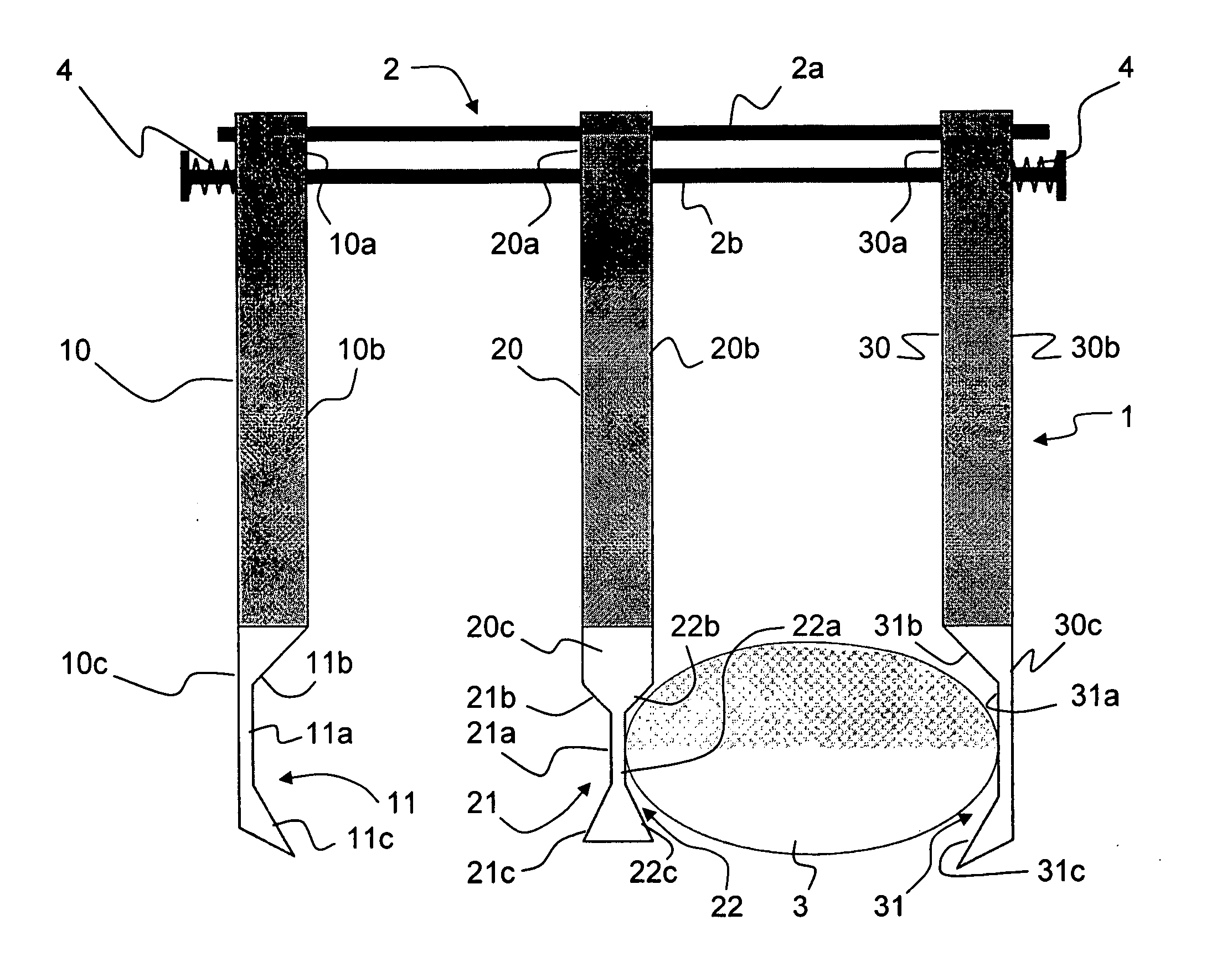
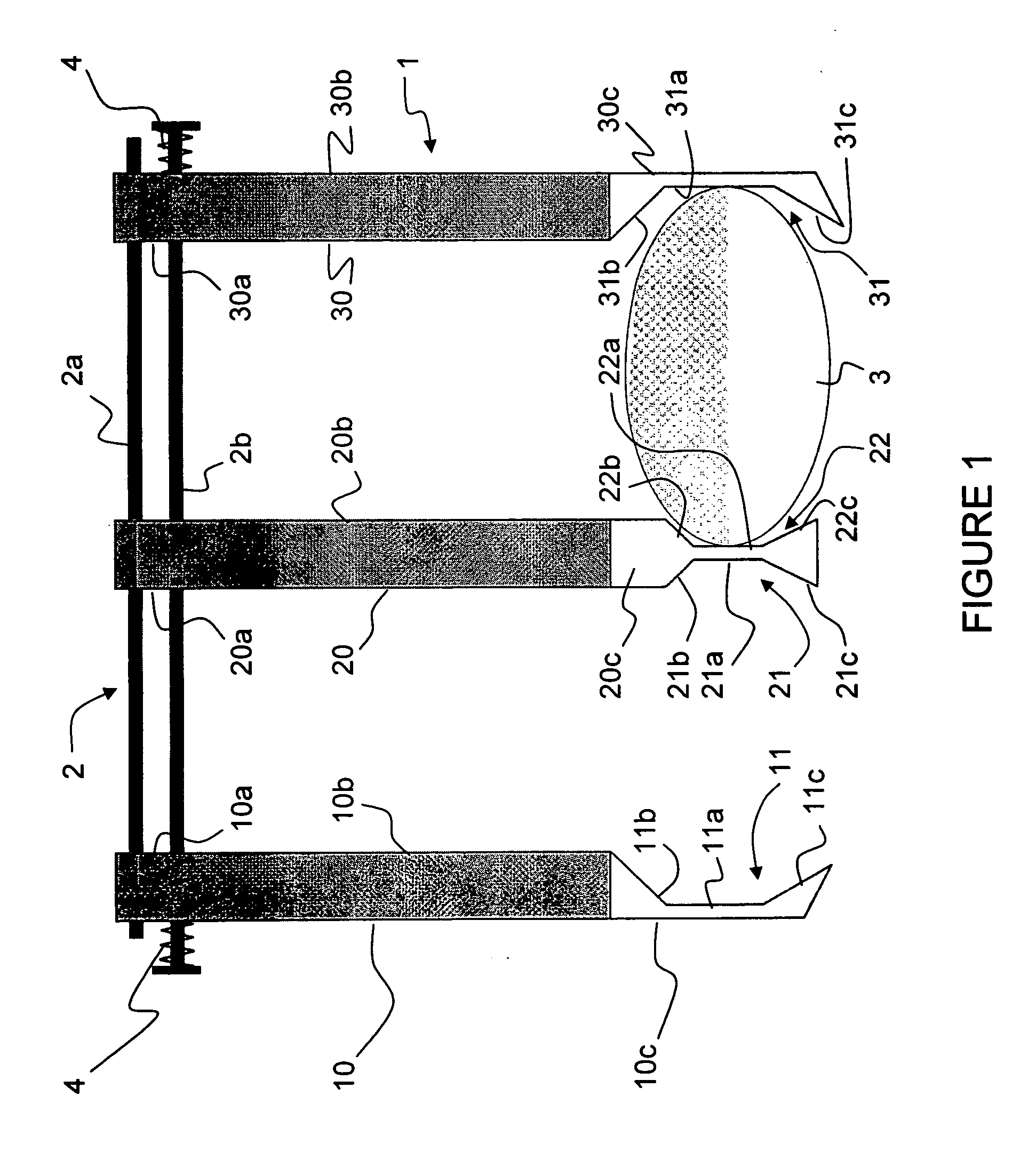
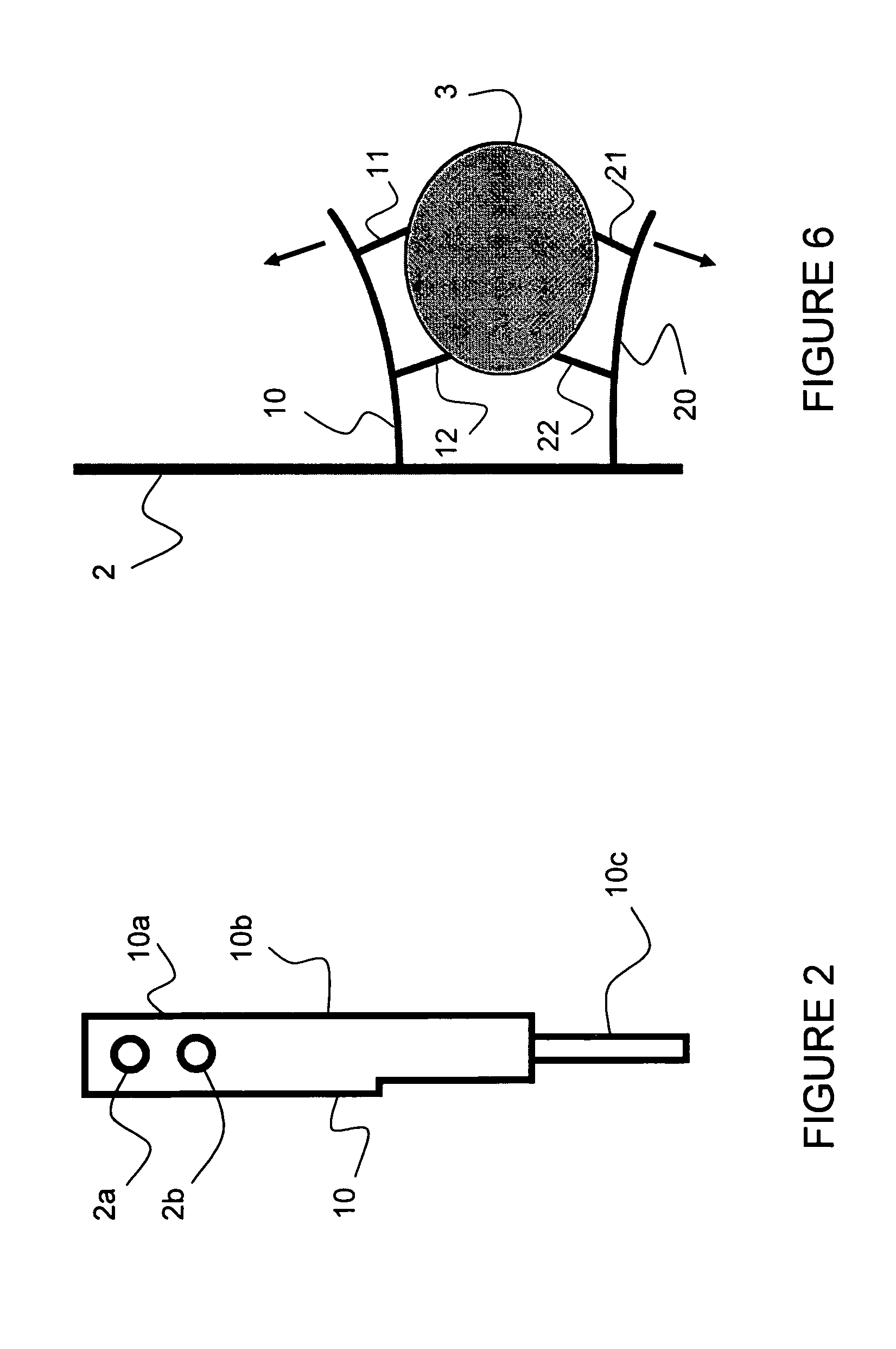
[0063] The holder used is as described on FIGS. 1 and 2.

[0064] The thickness of the parts 10c, 20c and 30c is 4 mm.

[0065] Burn marks are observed at the contact po...

example 2

[0066] Polycarbonate lens whose edge has a rectangular shape (after being edged by an edging machine) is placed in a lens holder according to the invention as shown in FIGS. 1 and 2 and is submitted to a corona discharge treatment.

[0067] The lens holder has arms made of DELRIN® with a 4 mm thickness of the lens accommodating portion, and an aluminum foil covering the lens accommodating portion of each arm.

[0068] The lens is passed in front of the corona heads at a speed of 17 mm / s, then is lowered down to 26 mm. This treatment is repeated 4 times. A delay of 5 s is observed between each passages (except when the lens is lowered down).

[0069] No defects are observed.


PUM

PropertyMeasurementUnit
dielectric constantaaaaaaaaaa
specific heataaaaaaaaaa
thicknessaaaaaaaaaa

Abstract

The invention relates to an optical lens holder comprising a supporting means and a first and a second arm defining a lens holder general plane, first and second arms being relatively movable with regards to each other and each arm having spaced apart first and second end portions and an intermediate portion, the arms being mounted on the supporting means through their first end portions and the second end portions of each arm comprising an optical lens accommodating means facing each other, whereby an optical lens can be maintained within the accommodating means of the first and second arms with its optical axis orthogonal to the general plane of the lens holder through at least one, preferably one or two contact points between the lens periphery and each of the first and second lens accommodating means, wherein at least the second end portion of each arm comprises a material having a dielectric constant at 1 MHz equal to or higher than the dielectric constant of the optical lens material.

Description

FIELD OF THE INVENTION [0001] The present invention relates to an optical lens holder, for holding one or more optical lenses, made of organic glass, in particular ophthalmic lenses, during treatments of the optical lenses, and in particular during a corona discharge treatment, which prevents damage to the optical lens such as burning or heat defects during a corona discharge treatment. BACKGROUND OF THE INVENTION [0002] Corona discharge is widely used to treat the surfaces of plastic parts such as organic glass optical lenses in order to improve the adhesion properties of the surfaces. In most cases, such parts are just placed on a belt or a similar device and the surface to be treated does not touch any other material. If the lens is submitted to several treatment steps then manual handling is generally required to put on and to take the lens off the belt. [0003] However, manual handling is troublesome. [0004] The object of the invention is to provide a new means for handling the ...

Claims


Application Information

Patent Timeline
Patent Type & Authority Applications(United States)
IPC IPC(8): C23C14/50G02B7/02
CPCG02B7/02
Inventor FOURNAND, GERALDREED, JAMES A.WRIGHT, DANNE
Owner ESSILOR INT CIE GEN DOPTIQUE
Why Eureka
Try Eureka