Novel integral type compact laser pipe cutting machine

A compact and integrated technology, applied in laser welding equipment, tubular objects, applications, etc., can solve problems such as complex structural design of pipe cutting machines, problems of pipe clamping adaptability, and inability to flexibly adjust pipe diameters, etc., to achieve improved Cutting efficiency and cutting quality, improving cutting quality, fast and convenient effect of receiving materials

Inactive Publication Date: 2017-09-15
DONGGUAN GLORYSTAR LASER TECH
View PDF7 Cites 19 Cited by
  • Summary
  • Abstract
  • Description
  • Claims
  • Application Information

AI Technical Summary

Problems solved by technology

[0003] The structure design of the traditional pipe cutting machine is relatively complicated, and is restricted by the shape of the pipe structure, so it needs to occupy a lot of space; in addition, the traditional pipe cutting machine mostly uses the grinding wheel as the pipe cutting execution part. During the cutting process, the pipe is linearly fed to the bottom of the grinding wheel, through The grinding wheel descends from the top surface of the pipe to the bottom surface to complete the cutting step by step. This cutting process has high requirements for the linear feeding accuracy of the grinding wheel and the movement accuracy of the grinding wheel. If there is a movement deviation, it will directly affect the flatness of the cutting surface of the pipe after cutting; in addition , in the actual cutting process, there is also the problem of pipe clamping adaptability. The diameter of the pipe that can be clamped by the ordinary pipe cutting machine cannot be adjusted flexibly, making it less versatile, and it is inconvenient to replace pipes with different diameters.

Method used


Image

  • Novel integral type compact laser pipe cutting machine
  • Novel integral type compact laser pipe cutting machine
  • Novel integral type compact laser pipe cutting machine

Examples


Embodiment Construction

[0044] The present invention will be further described below in conjunction with accompanying drawing:

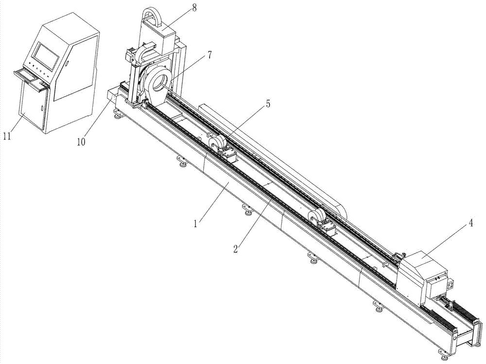
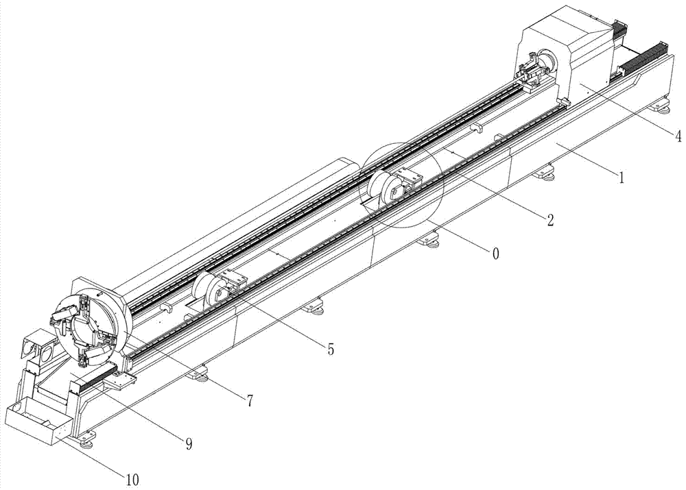
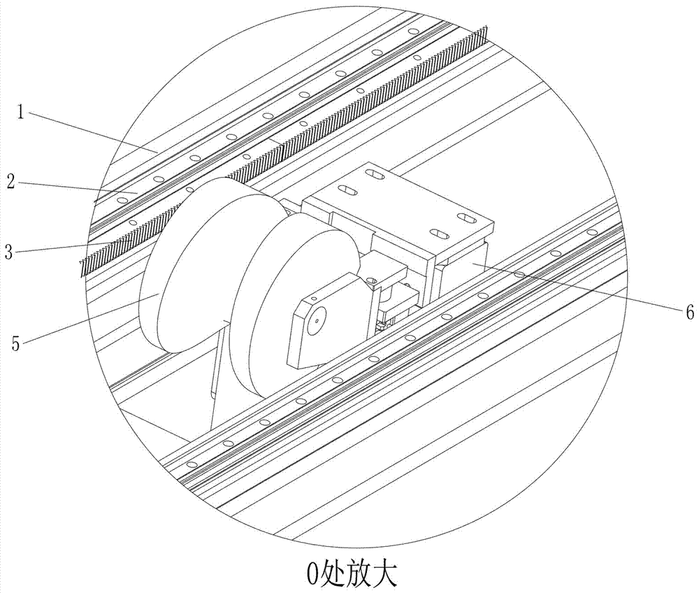
[0045] Such as Figure 1 to Figure 15 As shown, the technical solution adopted by the present invention is as follows: a new type of integrated compact laser pipe cutting machine, including a machine tool 1, a guide rail 2, a first clamping mechanism 4, a variable-diameter auxiliary support mechanism 5, and a second clamping mechanism 7 , cutting mechanism 8 and material box 10, wherein, above-mentioned machine tool 1 is a strip structure, and machine tool 1 is placed on the horizontal plane; Above-mentioned guide rail 2 comprises two, and two guide rails 2 are respectively arranged on the front and rear sides of machine tool 1 along the side direction of machine tool 1 The above-mentioned first clamping mechanism 4 is arranged on the rear end of the machine tool 1, and is slidably embedded on the guide rail 2. On the first clamping mechanism 4, one end of the pipe body to ...


PUM


Abstract

The invention discloses a novel integral type compact laser pipe cutting machine which comprises a machine tool, guide rails, a first clamping mechanism, reducing auxiliary supporting mechanisms, a second clamping mechanism, a cutting mechanism and a material box. The machine tool is of a strip-shaped structure. The two guide rails are arranged on the front side and the rear side of the machine tool correspondingly in the side edge direction of the machine tool. The first clamping mechanism is arranged at the rear end of the machine tool and embedded in the guide rails in a sliding manner. The first clamping mechanism clamps and fixes one end of a pipe body to be cut. At least two reducing auxiliary supporting mechanisms are arranged in the machine tool at intervals. The second clamping mechanism is fixedly arranged on the portion close to the front end of the machine tool. The second clamping mechanism fixes the other end of the pipe body to be cut. The cutting mechanism is arranged on the front side of the second clamping mechanism. The material box is arranged on the outer side of the front end of the machine tool. The novel integral type compact laser pipe cutting machine is compact in structure and small in space occupation rate, the pipe is driven to rotate to be cut at 360 degrees in the peripheral direction of the outer wall of the pipe body, and the cutting quality is effectively improved.

Description

technical field [0001] The invention relates to the field of mechanical automation, in particular to a novel integral compact laser pipe cutting machine. Background technique [0002] Pipe is a commonly used industrial raw material in modern industrial production. Pipe is used to make pipe fittings. Pipe fittings are widely used in construction, machinery industry, petroleum, agriculture and other fields; an indispensable process in the manufacturing process of pipe fittings is The cutting of the pipe is to cut the long pipe into pipe fittings of corresponding length according to the actual use requirements through the pipe cutting machine. [0003] The structure design of the traditional pipe cutting machine is relatively complicated, and is restricted by the shape of the pipe structure, so it needs to occupy a lot of space; in addition, the traditional pipe cutting machine mostly uses the grinding wheel as the pipe cutting execution part. During the cutting process, the pi...

Claims


Application Information

Patent Timeline
Patent Type & Authority Applications(China)
IPC IPC(8): B23K26/08B23K26/38B23K26/70B23K101/06
CPCB23K26/0846B23K26/38B23K26/702
Inventor 姚玉东郝英锋李荣飞何忠宝尹怀化
Owner DONGGUAN GLORYSTAR LASER TECH
Why Eureka
Try Eureka