Check patentability & draft patents in minutes with Patsnap Eureka AI!

Feeding device for refractory material combustion chamber

A technology of refractory materials and feeding devices, which is applied in the direction of furnace materials, lighting and heating equipment, furnace types, etc., can solve the problems of no directional fuel addition, slow combustion, uneven local combustion, etc., to increase temperature and prevent excessive fuel delivery Effect

Pending Publication Date: 2017-09-15
浙江中茂耐火材料有限公司
View PDF6 Cites 0 Cited by
  • Summary
  • Abstract
  • Description
  • Claims
  • Application Information

AI Technical Summary

Problems solved by technology

[0002] During the sintering process of refractory materials, a large amount of fuel is used to burn them. During the combustion process, the fuel will burn unevenly locally. The fuel in the combustion chamber will burn too fast in some places in the combustion chamber, while in some places it will Too slow, so it is necessary to add fuel to the place where the combustion is too fast, and there is no device for directional fuel addition in the prior art

Method used


Image

  • Feeding device for refractory material combustion chamber
  • Feeding device for refractory material combustion chamber
  • Feeding device for refractory material combustion chamber

Examples


Embodiment Construction

[0022] The specific implementation manners of the present invention will be further described in detail below in conjunction with the accompanying drawings and embodiments. The following examples are used to illustrate the present invention, but are not intended to limit the scope of the present invention.

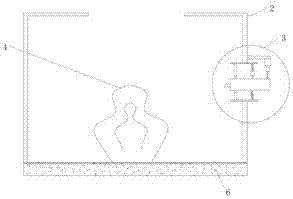
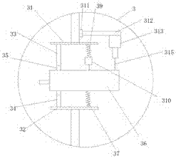
[0023] see Figure 1 to Figure 3 , a refractory material combustion chamber charging device described in a preferred embodiment of the present invention, a refractory material combustion chamber charging device, comprising a combustion chamber 2, fuel 6 is stacked at the bottom of the combustion chamber 2,

[0024] An injection device 3 is provided on the side of the combustion chamber 2, and the injection device 3 is used to inject fuel 6;

[0025] The injection device 3 includes a spray tank 36, the spray tank 36 is a cylindrical tank, the spray tank 36 is at least partly located inside the combustion chamber 3, and the spray tank 36 has a nozzle 361 , the spray nozzle...


PUM


Abstract

The invention relates to a feeding device for a refractory material combustion chamber. The feeding device for the refractory material combustion chamber comprises the combustion chamber (2); fuel (6) is piled up at the bottom of the combustion chamber (2); an injecting device (3) is arranged on the side face of the combustion chamber (2), and is used for injecting the fuel (6); the injecting device (3) comprises a fuel injecting tank (36) which is provided with an injecting head (361); the injecting head (361) is arranged in the combustion chamber (2); the fuel injecting tank (36) is further connected with a compressed air tank (316) which is used for injecting high-pressure air into the fuel injecting tank (36); and the fuel injecting tank (36) is further connected with a fuel storing tank (317) which is used for accurately conveying the fuel (6) into the fuel injecting tank (36). By means of the feeding device for the refractory material combustion chamber, the fuel can be accurately conveyed into the combustion chamber.

Description

technical field [0001] The invention relates to a control device, in particular to a refractory material temperature control device. Background technique [0002] During the sintering process of refractory materials, a large amount of fuel is used to burn them. During the combustion process, the fuel will burn unevenly locally. The fuel in the combustion chamber will burn too fast in some places in the combustion chamber, while in some places it will Too slow, so it is necessary to add fuel to the place where the combustion is too fast, and there is no device for directional fuel addition in the prior art. [0003] In view of the above-mentioned defects, the designer actively researches and innovates in order to create a refractory material combustion chamber feeding device with a new structure, so that it has more industrial utilization value. Contents of the invention [0004] In order to solve the above technical problems, the object of the present invention is to prov...

Claims


Application Information

Patent Timeline
Patent Type & Authority Applications(China)
IPC IPC(8): F27B21/08F27D99/00
CPCF27B21/00F27D99/0001F27M2003/04
Inventor 费海龙
Owner 浙江中茂耐火材料有限公司
Features
  • R&D
  • Intellectual Property
  • Life Sciences
  • Materials
  • Tech Scout
  • Unparalleled Data Quality
  • Higher Quality Content
  • 60% Fewer Hallucinations
Learn More