
Ecological building optical refraction system

An ecological building and optical technology, applied in the field of optical refraction systems for ecological buildings, can solve problems such as affecting the utilization rate of light energy, water seepage failure of photovoltaic power generation equipment, and inability of photovoltaic power generation equipment to use building lighting, etc., to ensure the utilization rate of light energy, The effect of alleviating water seepage failure and saving energy loss

Inactive Publication Date: 2017-09-15
曹华
View PDF3 Cites 0 Cited by
  • Summary
  • Abstract
  • Description
  • Claims
  • Application Information

AI Technical Summary

Problems solved by technology

[0003] The present invention aims at the technical defects of the prior art, and provides an ecological building optical refraction system to solve the problem that the photovoltaic power generation equipment of the prior art cannot be used for building lighting
[0004] Another technical problem to be solved by the present invention is the internal water seepage failure of the photovoltaic power generation equipment installed on buildings in the prior art due to rainfall
[0005] Another technical problem to be solved by the present invention is that in the prior art, the surface of photovoltaic power generation equipment installed on buildings will affect the utilization rate of light energy due to the deposition of dust.

Method used


Image

  • Ecological building optical refraction system
  • Ecological building optical refraction system
  • Ecological building optical refraction system

Examples


Embodiment 1

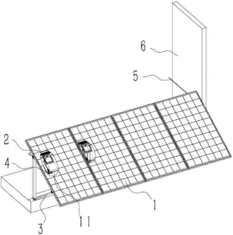
[0021] This embodiment describes a kind of ecological building optical refraction system, its overall structure is as follows figure 1 As shown, the refraction system includes a photovoltaic panel assembly 1 and a grid-connected inverter 2, the photovoltaic panel assembly 1 is connected to the DC input terminal 7 of the grid-connected inverter 2 separately, and the refraction system also includes a photovoltaic panel The module installation bracket 3, the photovoltaic panel assembly 1 is fixed on the exterior wall of the building 6 through the photovoltaic panel assembly installation bracket 3, and the photovoltaic panel assembly installation bracket 3 is installed on the sunny side of the building 6 exterior wall.

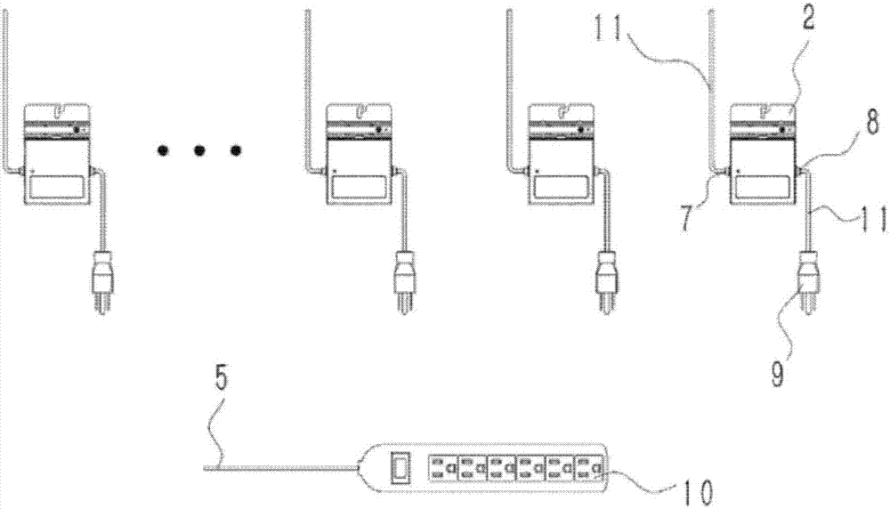
[0022] In this embodiment, the grid-connected inverter 2 can be connected to the grid through the power socket 10, and its wiring diagram is as follows figure 2 As shown, the AC output terminal 8 of the grid-connected inverter 2 is directly inserted into the powe...

Embodiment 2

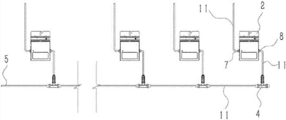
[0026] An optical refraction system for an ecological building, including a photovoltaic cell panel assembly and a grid-connected inverter, and the photovoltaic cell panel assembly is separately connected to the input end of the grid-connected inverter; the refraction system also includes a photovoltaic cell panel assembly mounting bracket, the The photovoltaic cell panel assembly is fixed on the building exterior wall through the photovoltaic cell panel assembly mounting bracket, and the photovoltaic cell panel assembly mounting bracket is installed on the sunny side of the building exterior wall; the output end of the grid-connected inverter is inserted into the The power socket on the power grid; the refraction system also includes an external municipal power grid, and the grid-connected inverter is provided with an AC access node, and the grid-connected inverter is first connected in parallel through the AC access node and then connected to the grid. The refraction system a...


PUM


Abstract

The invention provides an ecological building optical refraction system. According to the system, the natural light is guided into the indoor through curved mirror refraction by using concave-convex light reflection equipment through reference to the optical refraction principle so that each indoor corner is enabled to receive the natural light. The solar photoelectric technology is suitable for household use. One set of solar photoelectric 12V power generating and lighting equipment is installed, and continuous lighting of 72h can be realized by charging for 1h under the condition of sufficient sunlight so that the technical problem of high cost of the present photovoltaic power generating enterprises can be broken through, low energy and high efficiency can be realized and the technology is mature and internationally approved. According to the system, 12V direct current can be inverted into 110V, and inversion of 220 alternating current is in the test phase and promoted to the domestic and foreign markets soon. The German technology is introduced in the project, which is the global leader and unique at home; light energy power generation is green and environment-friendly and simple and convenient; lighting of 72h can be realized by charging for 1h so as to be efficient and long-acting; and the cost can be saved and the cost performance is high so that household lighting can be realized by using the equipment.

Description

technical field [0001] The invention relates to the technical field of optical power generation, and further relates to photoelectric lighting technology, in particular to an optical refraction system for ecological buildings. Background technique [0002] With the development of the photovoltaic industry, photovoltaic power generation has gradually extended from the industrial field to the civilian field. Due to the limited space of the building itself, the number of photovoltaic panels installed is limited. In the traditional grid-connected power generation system, when the number of solar panels installed is low to a certain extent, the output voltage becomes low, which seriously restricts the power generation efficiency of the grid-connected system, and even the inverter in the traditional grid-connected power generation system cannot be started to work. When the inverter fails to work, the electricity generated by the photovoltaic panel components cannot be converted an...

Claims


Application Information

Patent Timeline
Patent Type & Authority Applications(China)
IPC IPC(8): H02J3/38H02S40/30H02S20/22F21V33/00
CPCF21V33/00H02J3/383H02S20/22H02S40/30Y02B10/10Y02E10/56Y02P80/20
Inventor 曹华吴清明高宸王恒涛凌宗权曹权
Owner 曹华
Learn More