Supercharge Your Innovation With Domain-Expert AI Agents!

Permanent magnet motor rotor punching sheet structure

A rotor punching, permanent magnet motor technology, applied in the shape/style/structure of the magnetic circuit, the rotating parts of the magnetic circuit, the magnetic circuit, etc., can solve the problem of material waste, and achieve uniform magnetic field density, small space, and strong magnetic field. Effect

Inactive Publication Date: 2017-09-15
无锡泓阳电动科技有限公司
View PDF2 Cites 2 Cited by
  • Summary
  • Abstract
  • Description
  • Claims
  • Application Information

AI Technical Summary

Problems solved by technology

[0003] However, since the magnetic field generated by the permanent magnets in the rotor is related to the relative position between the permanent magnet leakage space and the permanent magnets, if there is a large gap between the permanent magnets, it will cause waste of materials

Method used


Image

  • Permanent magnet motor rotor punching sheet structure

Examples


Embodiment Construction

[0014] The technical solutions of the present invention will be further described below in conjunction with the accompanying drawings and through specific implementation methods.

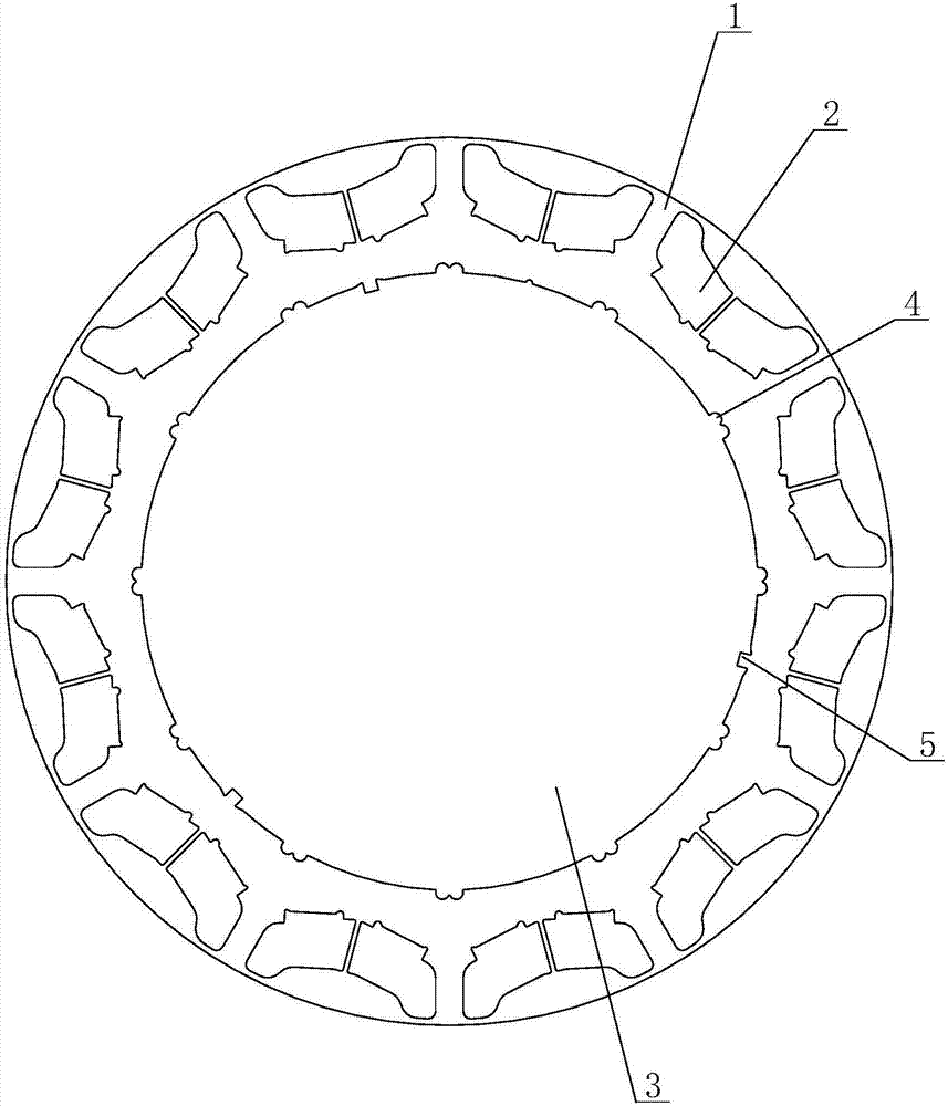
[0015] see figure 1 as shown, figure 1 It is a structural schematic diagram of the punching structure of the permanent magnet motor rotor provided in Embodiment 1 of the present invention.

[0016] In this embodiment, a permanent magnet motor rotor stamping structure includes a rotor stamping formed by a silicon steel sheet 1, a permanent magnet 2, a welding groove 4, and a positioning groove 5. There are gaps at a certain distance, the rotor punch has 24 slots, the outer diameter of the rotor punch is 255mm-260mm, the slot width of the slot is 16mm-18mm, the upper top surface of the slot to the rotor The outer circle of the stamping sheet has a closed section of 2mm-5mm, and the distance between two adjacent grooves is 1mm-3mm, which produces a stronger and more uniform magnetic field, which is m...


PUM

PropertyMeasurementUnit
Diameteraaaaaaaaaa
Notch widthaaaaaaaaaa
Diameteraaaaaaaaaa

Abstract

The invention discloses a permanent magnet motor rotor punching sheet structure, which comprises a rotor punching sheet formed by splicing a silicon steel sheet, welding slots, permanent magnets and positioning slots, and is characterized in that the center of the rotor punching sheet is provided with a shaft hole, the rotor punching sheet is provided with 24 slots, the excircle diameter of the rotor punching sheet is 255mm-260mm, the slot opening width of the slots is 16mm-18mm, a 2mm-5mm closed section is reserved between the upper top surface of the slot opening and the excircle of the rotor punching sheet, and the distance between two adjacent slots is 1mm-3mm. According to the permanent magnet motor rotor punching sheet structure, a magnetic field generated by the adjacent permanent magnets is stronger, more stable and more uniform, the occupied space is smaller, the permanent magnets are sufficiently utilized, slots with the slot opening being appropriate are selected to improve the magnetic field capacity of a motor under the protection intensity, stable current is generated, the magnetic field density of the rotor punching sheet is enabled to be uniform under the optimized and reasonable structure design, thus a rotor is more stable in rotation, the noise is reduced, and materials are saved.

Description

technical field [0001] The invention relates to a rotor stamping, in particular to a permanent magnet motor rotor stamping structure. Background technique [0002] The permanent magnet of the rotor structure is located inside the rotor, and there is a pole piece made of ferromagnetic material (usually laminated silicon steel sheet) between the outer surface of the permanent magnet and the inner circle of the stator core, which helps to improve the motor's performance by using the reluctance torque. Overload capacity and power density, and easy to expand the speed of the field weakening. Therefore, this type of rotor is widely used in permanent magnet motors. [0003] However, since the magnetic field generated by the permanent magnets in the rotor is related to the relative position between the permanent magnet flux leakage space and the permanent magnets, if there is a large difference in the positions between the permanent magnets, it will cause waste of materials. Cont...

Claims


Application Information

Patent Timeline
IPC IPC(8): H02K1/27
CPCH02K1/27H02K2201/15H02K2213/03
Inventor 陈泓
Owner 无锡泓阳电动科技有限公司
Features
  • R&D
  • Intellectual Property
  • Life Sciences
  • Materials
  • Tech Scout
  • Unparalleled Data Quality
  • Higher Quality Content
  • 60% Fewer Hallucinations
Learn More