
A pressure difference lung capacity measuring device

A measuring device and spirometric technology, which are applied in the field of spirometric measurement and can solve the problems of inability to objectively and accurately represent the volume of exhaled air, inability to exhale residual air of the patient under test, and adverse effects on measurement accuracy.

Active Publication Date: 2020-02-21
NANYANG NORMAL UNIV
View PDF4 Cites 0 Cited by
  • Summary
  • Abstract
  • Description
  • Claims
  • Application Information

AI Technical Summary

Problems solved by technology

[0003] However, there are the following problems in the existing drainage-type vital capacity measuring device: 1. During the exhalation process of the patient under test, the liquid level in the water storage container continues to drop, and the resistance suffered by the patient's exhalation increases with that in the water storage container. The liquid level decreases and increases, and at the same time, the pressure in the lungs is low in the late stage of exhalation, so that the patient under test cannot exhale the remaining air, which has a negative impact on the measurement accuracy; 2. The gas pressure in the water storage container is not equal to the normal atmospheric pressure, which is abnormal The volume change of the gas in the water storage container under the atmospheric pressure environment is not equal to the exhaled gas volume of the measured object in the normal atmospheric pressure environment. Therefore, the volume of the discharged water cannot objectively and accurately represent the volume of the exhaled gas in the normal atmospheric pressure environment

Method used


Image

  • A pressure difference lung capacity measuring device
  • A pressure difference lung capacity measuring device
  • A pressure difference lung capacity measuring device

Examples


Embodiment 1

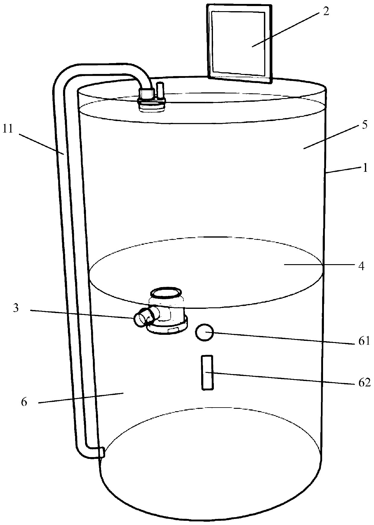
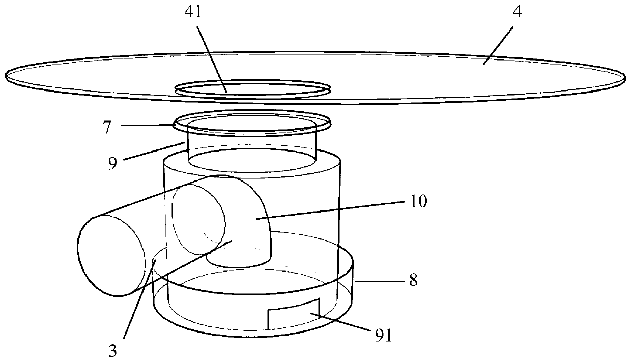
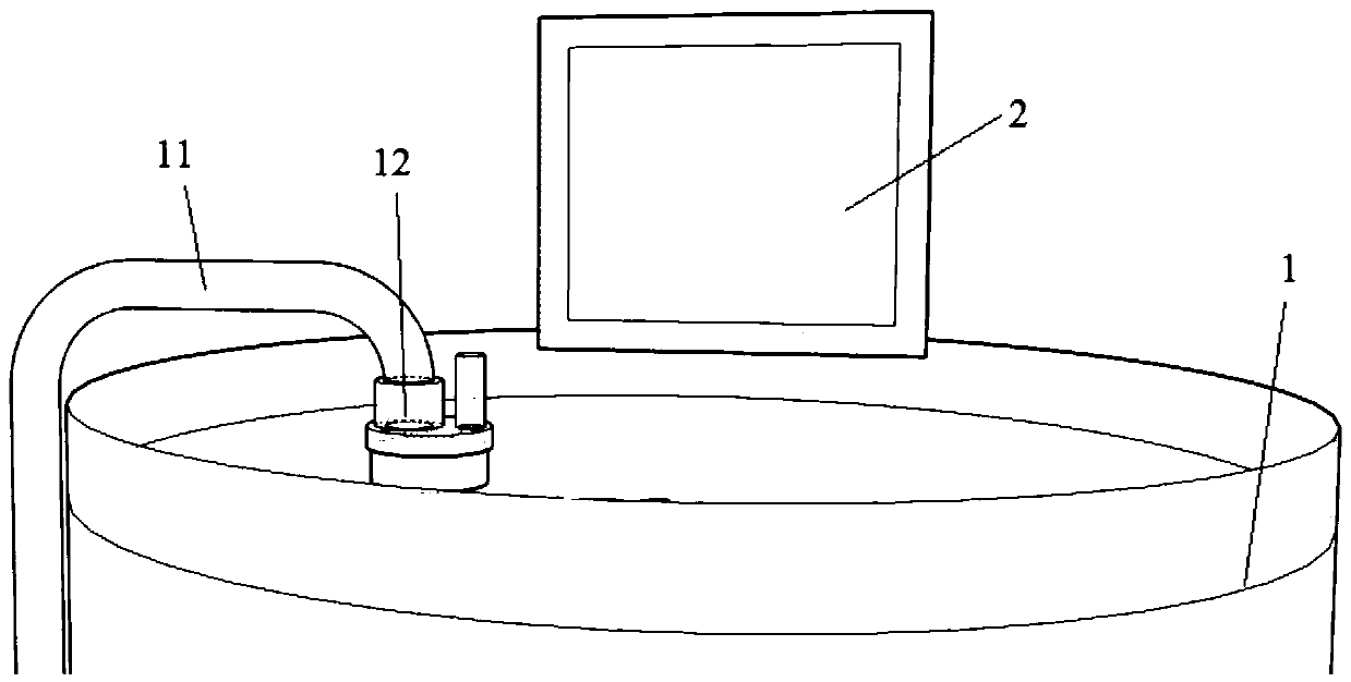
[0018] Embodiment one: if Figure 1-Figure 3As shown, a differential pressure vital capacity measuring device includes a box body 1, a pumping assembly, a pressure detection assembly, a controller, a display screen 2, a drainage assembly and an air guide tube 3; the pressure detection assembly and the display screen 2 are respectively connected to the controller , the box 1 is provided with a partition 4, the partition 4 divides the box 1 into a measurement chamber 5 and a water storage chamber 6, the measurement chamber 5 is located above the water storage chamber 6, and the side wall of the water storage chamber 6 is set There is a water injection port 61, and the partition 4 is provided with an opening 41 for communicating with the measurement chamber 5 and the water storage chamber 6; the pressure detection assembly includes two pressure sensors arranged in the measurement chamber 5, and one pressure sensor is installed on the The upper end is used to detect the upper gas ...

Embodiment 2

[0020] Embodiment two: if Figure 1-Figure 3 As shown, a differential pressure vital capacity measuring device includes a box body 1, a pumping assembly, a pressure detection assembly, a controller, a display screen 2, a drainage assembly and an air guide tube 3; the pressure detection assembly and the display screen 2 are respectively connected to the controller , the box 1 is provided with a partition 4, the partition 4 divides the box 1 into a measurement chamber 5 and a water storage chamber 6, the measurement chamber 5 is located above the water storage chamber 6, and the side wall of the water storage chamber 6 is set There is a water injection port 61, and the partition 4 is provided with an opening 41 communicating with the measurement chamber 5 and the water storage chamber 6; the pressure detection assembly includes two pressure sensors arranged in the measurement chamber 5, and one pressure sensor is installed The upper end is used to detect the upper gas pressure i...

Embodiment 3

[0023] Embodiment three: as Figure 1-Figure 3 As shown, a differential pressure vital capacity measuring device includes a box body 1, a pumping assembly, a pressure detection assembly, a controller, a display screen 2, a drainage assembly and an air guide tube 3; the pressure detection assembly and the display screen 2 are respectively connected to the controller , the box 1 is provided with a partition 4, the partition 4 divides the box 1 into a measurement chamber 5 and a water storage chamber 6, the measurement chamber 5 is located above the water storage chamber 6, and the side wall of the water storage chamber 6 is set There is a water injection port 61, and the partition 4 is provided with an opening 41 communicating with the measurement chamber 5 and the water storage chamber 6; the pressure detection assembly includes two pressure sensors arranged in the measurement chamber 5, and one pressure sensor is installed The upper end is used to detect the upper gas pressure...


PUM


Abstract

The invention discloses a pressure difference type vital capacity measuring device. The pressure difference type vital capacity measuring device comprises a box body, a water pumping assembly, a pressure intensity detection assembly, a controller, a display screen, a draining assembly and an air guide tube, wherein the pressure intensity detection assembly and the display screen are respectively connected with the controller, a baffle plate is arranged in the box body, the inside of the box body is divided by the baffle plate into a measuring chamber and a water storage chamber, an opening is formed in the baffle plate, the draining assembly comprises a cannula, a water tank and a first electric control valve, the cannula is arranged at the opening, the water tank is positioned in the water storage chamber, the first electric control valve is arranged in the water tank, the electric control end of the first electric control valve is connected with the controller, one end of a passage of the first electric control valve is connected with the cannula, a draining hole is formed in the side wall of the passage of the first electric control valve, the draining hole is lower than the upper end surface of the water tank in height, an equalizing tube is arranged along the vertical direction in a water inlet passage of the first electric control valve, the lower end surface of the equalizing tube is flush with the upper end surface of the water tank, and the upper end of the equalizing tube is connected with one end of the air guide tube. The pressure difference type vital capacity measuring device has the advantage of relatively high measuring accuracy.

Description

technical field [0001] The invention relates to a vital capacity measurement technology, in particular to a differential pressure type vital capacity measurement device. Background technique [0002] At present, it is of great significance to measure vital capacity to judge the nature and degree of certain respiratory function reduction of patients, as well as the working ability of patients after recovery from the disease. The drainage-type spirometry device has been widely used in the field of spirometry because of its simple structure, low manufacturing cost and environmental protection. The existing drainage type spirometry device usually includes a water storage container and a pipeline, and the pipeline is connected to the bottom of the water storage container and communicated with the water storage container. Before use, put water into the water storage container and the pipeline, keep the nozzle of the pipeline horizontal, and the liquid level in the water storage c...

Claims


Application Information

Patent Timeline
Patent Type & Authority Patents(China)
IPC IPC(8): A61B5/091
CPCA61B5/091
Inventor 李宝磊冯桂玲朱永胜侯书进翟静于明渊
Owner NANYANG NORMAL UNIV
Learn More