Charging pile for electric automobile

A technology for electric vehicles and charging piles, which is applied in electric vehicle charging technology, electric vehicles, charging stations, etc., can solve the problems of easily reducing the service life of cables and being susceptible to wind and sun, so as to prevent the cables from falling off and solve the Too loose to ensure a fixed effect

Inactive Publication Date: 2017-09-19
HANGZHOU LEE POOL TECH CO LTD
View PDF5 Cites 10 Cited by
  • Summary
  • Abstract
  • Description
  • Claims
  • Application Information

AI Technical Summary

Problems solved by technology

[0004] The purpose of the present invention is to provide a charging pile for electric vehicles to solve the problem that the cables on the existing charging piles for automobiles are easily exposed to the wind and the sun when not in use, thereby reducing the service life of the cables. lead to potential safety hazards

Method used


Image

  • Charging pile for electric automobile
  • Charging pile for electric automobile
  • Charging pile for electric automobile

Examples


Embodiment 1

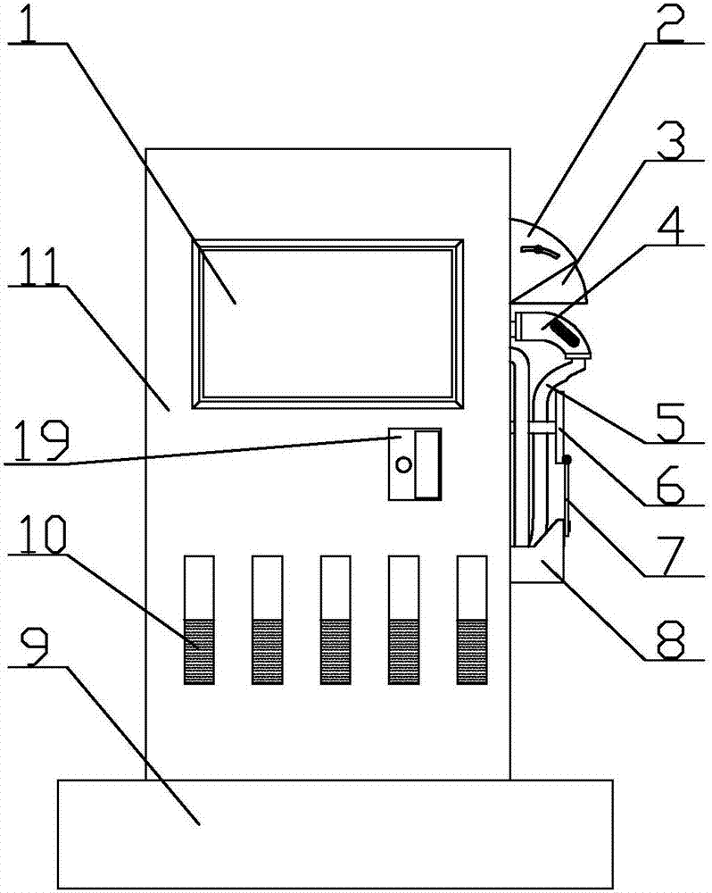
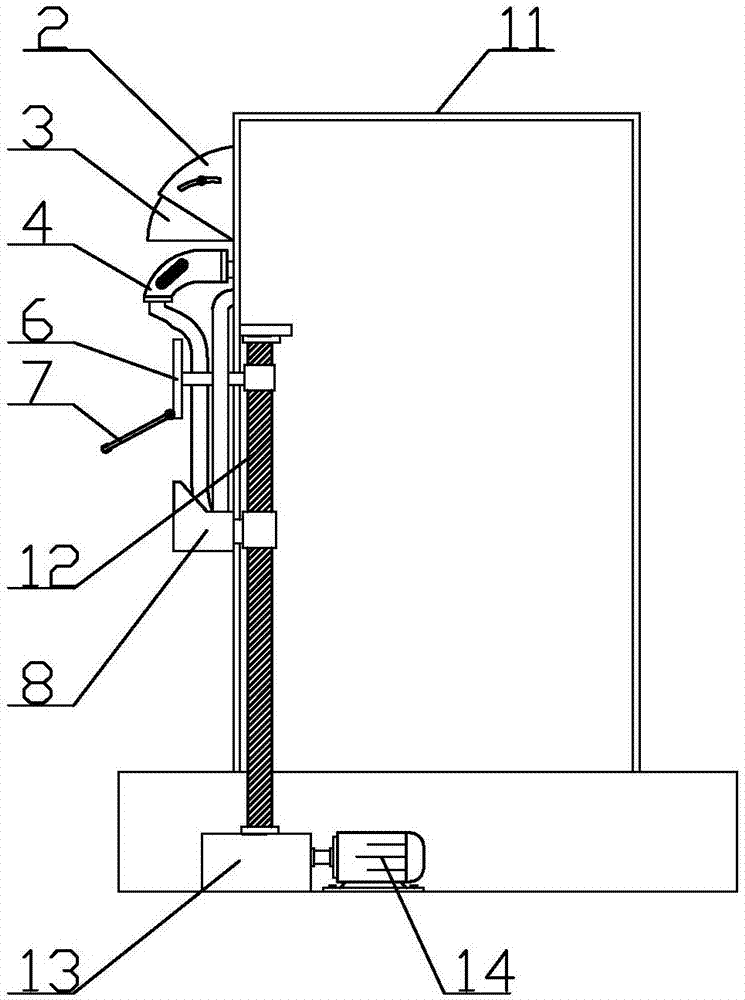
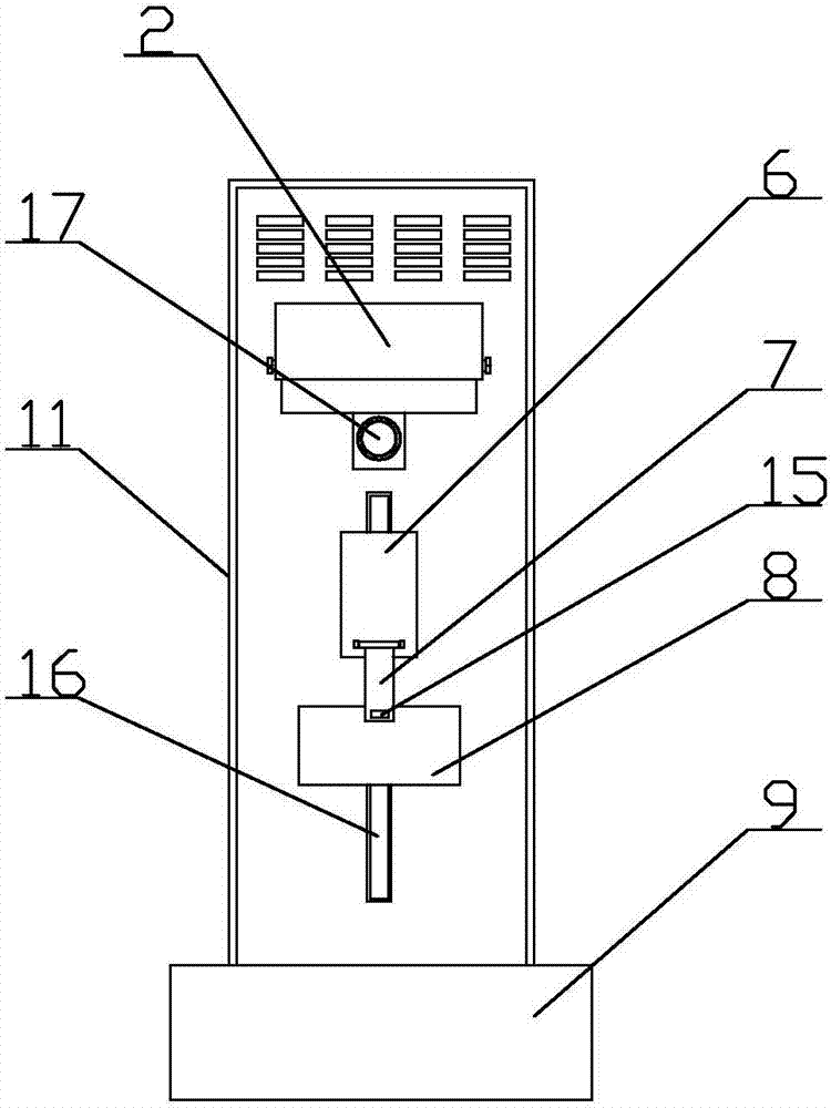
[0039] see figure 1 , figure 2 and image 3 , the present invention provides a technical solution: an electric vehicle charging pile, including a charging gun 4 and a charging pile casing 11, a display screen 1 is provided on the upper front surface of the charging pile casing 11, and the front surface of the charging pile casing 11 is close to the display A reflective strip 10 is provided under the screen 1, a charging pile base 9 is provided at the bottom of the charging pile housing 11, and a fixed protective cover 2 is provided on one side of the charging pile housing 11, and a movable protective cover 2 is provided on the inner side of the fixed protective cover 2. Type protective cover 3, one side of the charging pile shell 11 close to the bottom of the fixed protective cover 2 is provided with a charging gun fixing slot 17, the charging gun 4 is installed inside the charging gun fixing slot 17, and the charging gun 4 is far away from the charging pile shell 11 A char...

Embodiment 2

[0047] combine Figure 4 to Figure 7 As shown, the present embodiment makes the following improvements on the basis of embodiment 1:

[0048] A password input device 19 for identifying user identity is installed on the front surface of the charging pile housing below the display screen. When using the charging pile for the first time, use the mobile phone to scan the QR code on the display screen for account registration and recharge, etc., and then set the password through the password input device. In subsequent uses, you only need to enter it directly on the password input device on the charging pile. Password can be charged. The charging pile deducts money from the corresponding account according to the charging time.

[0049] The password input device includes a first housing 91, a second housing 92 and a cover plate 93 connected in sequence; a finger insertion port 912 through the front and back is formed on the first housing, An installation cavity 914 is formed on t...


PUM


Abstract

The invention discloses a charging pile for an electric automobile. The charging pile for the electric automobile comprises a charging gun and a charging pile housing, wherein a display screen is arranged on the upper end of the front surface of the charging pipe housing, and a reflective stripe is arranged at a lower side, close to the display screen, of the front surface of the charging pile housing; a charging pile base is arranged at the bottom of the charging pile housing, and a fixed protective cover is arranged at the upper end on one side of the charging pile housing; a movable protective cover is arranged on the inner side of the fixed protective cover; a charging gun fixing groove is formed in the lower side, close to the fixed protective cover, of one side of the charging pile housing; and the charging gun is mounted in the charging gun fixing groove. By designing a roller lead screw connected to a cable winding rack and a driving motor in the charging pile housing, a user drives a cable to be close to the fixed protective cover after use, so that the cable is protected by the protective cover to the maximum extent, and the problem that the cable is damaged as the cable is directly dragged on the ground is solved.

Description

technical field [0001] The invention belongs to the technical field of automobile charging piles, and in particular relates to an electric automobile charging pile. Background technique [0002] The function of the charging pile is similar to that of the fuel dispenser in the gas station. It can be fixed on the ground or on the wall, and installed in public buildings (public buildings, shopping malls, public parking lots, etc.) and residential area parking lots or charging stations. Charge all models of electric vehicles. The input end of the charging pile is directly connected to the AC grid, and the output end is equipped with a charging plug for charging the electric vehicle. Charging piles generally provide two charging methods: conventional charging and fast charging. People can use a specific charging card to swipe the card on the human-computer interaction interface provided by the charging pile to perform corresponding charging methods, charging time, and cost data ...

Claims


Application Information

Patent Timeline
Patent Type & Authority Applications(China)
IPC IPC(8): B60L11/18G07C9/00F21V33/00
CPCB60L53/16B60L53/31F21V33/00G07C9/00563G07C9/00896Y02T10/70Y02T10/7072Y02T90/12Y02T90/14
Inventor 江佳辉
Owner HANGZHOU LEE POOL TECH CO LTD
Why Eureka
Try Eureka