
Battery thermal runaway protecting part and preparation method as well as die thereof

A technology of protective parts and thermal runaway, applied in battery pack components, isolation of batteries from their environment, electrical components, etc., can solve the problems of high cavity strength and sealing performance requirements, unsatisfactory flame retardant effect, cumbersome process, etc. The casting method is simple and easy to implement, preventing the spread of thermal runaway, and improving the effect of safety performance

Active Publication Date: 2017-09-19
CHINA ELECTRIC POWER RES INST +2
View PDF17 Cites 3 Cited by
  • Summary
  • Abstract
  • Description
  • Claims
  • Application Information

AI Technical Summary

Problems solved by technology

[0006] The flame retardant materials of the existing lithium-ion batteries are mostly coated on the positive and negative electrodes and separators inside the lithium-ion battery by coating. Although this method can partially slow down the ignition and combustion of lithium-ion batteries Or containment effect, but due to the arrangement in the limited space inside the battery, the shape and quality of the flame retardant material are affected. Generally, the thickness of the coating layer is only 0.5-10μm, resulting in unsatisfactory flame retardant effect. At the same time, due to the flame retardant The coating applied on the positive and negative plates or diaphragm of the battery will inevitably affect the capacity, power performance or other electrical properties of the battery itself
In addition, there is also a method of adding a flame retardant as an additive to the electrolyte of a lithium-ion battery to control or block the flame generated when the lithium-ion battery is thermally runaway. This method also places a flame-retardant material inside the battery to reduce the The flame retardant effect is not good, and it is not conducive to the ion conductance of the battery electrolyte, which leads to a decline in the electrical performance of the battery
In addition, there is also a method of encapsulating the lithium-ion battery in a closed rigid cavity and passing an inert gas inside. Although this method can effectively curb the spread of thermal runaway of the lithium-ion battery, it requires high strength and sealing performance of the cavity. are high, and the heavy rigid shell, cumbersome process and high cost constitute the bottleneck of the promotion and use of this method

Method used


Image

  • Battery thermal runaway protecting part and preparation method as well as die thereof
  • Battery thermal runaway protecting part and preparation method as well as die thereof
  • Battery thermal runaway protecting part and preparation method as well as die thereof

Examples


Embodiment 1

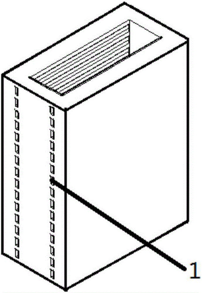
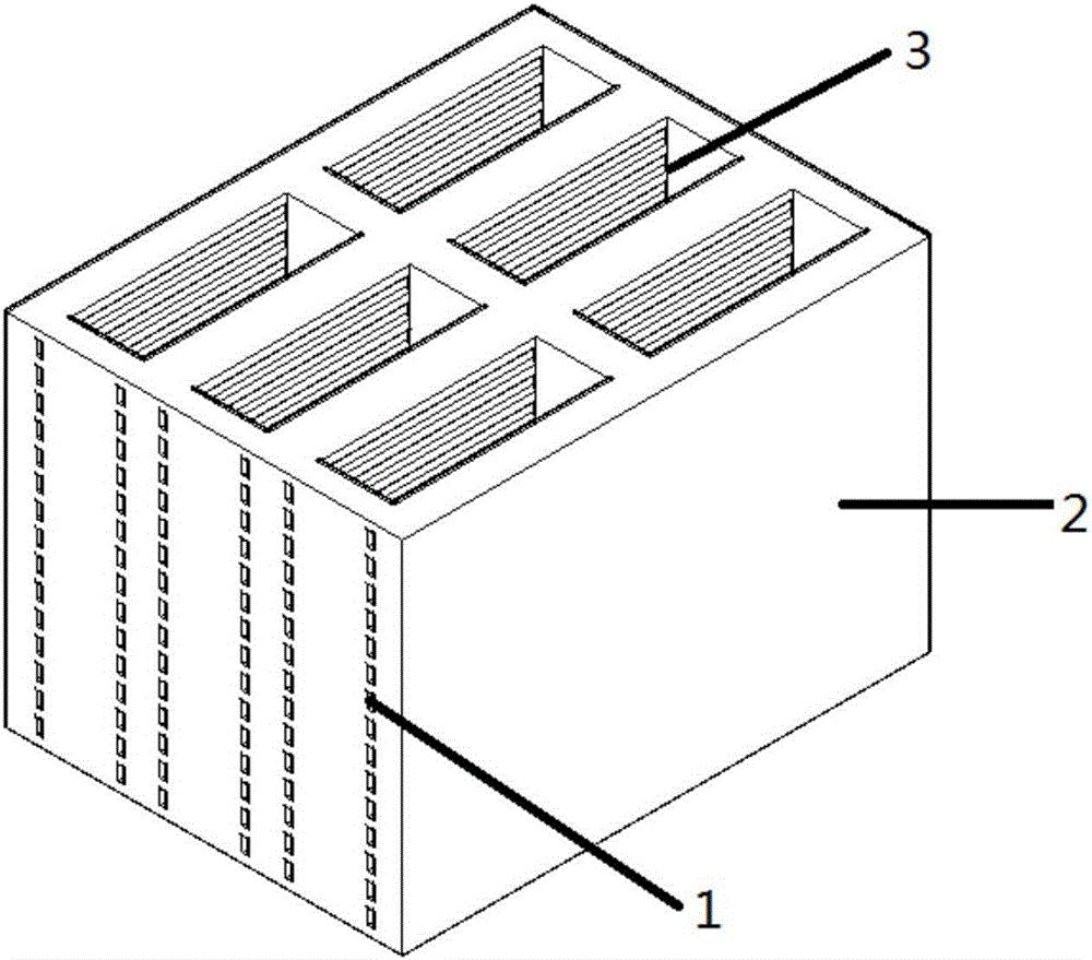
[0042] Such as Figure 1-3 As shown, it is a structural schematic diagram of a battery thermal runaway protection part and its preparation method and mold provided by the present invention. The protection part can be composed of one or more heat insulation units, and the combination method can be determined according to actual needs. The heat insulation unit It is in the shape of a cuboid, and the cuboid is a cuboid frame with a group of parallel plane openings. A channel 1 parallel to the axial direction of the heat insulation unit is arranged in a group of side walls opposite to the cuboid. The wall is perpendicular to the wall; the side arm of the cuboid is a laminated structure, and the laminated structure includes an outer layer, a middle layer and an inner layer, wherein the outer layer is a heat insulation board, the middle layer is a flame retardant board, and the inner layer is a pouring frame.

[0043]The heat insulation unit is equipped with a temperature alarm to a...

Embodiment 2

[0050] Such as image 3 As shown, it is a schematic diagram of the mold structure for preparing the inner pouring frame of the battery protection part. The mold is made of stainless steel or other metals with a melting point higher than 500 °C or their alloys, including: four surrounding plates 4, and a bottom plate 5 perpendicular to the surrounding plates 4 , battery model 6, and bolts 7 and nuts 8 used around.

[0051] Among them, the coaming plate 4 is welded by 90 cuboid steel bars and a steel plate, and the welding spacing and distribution of the steel bars are as follows: Figure 4 shown. Two symmetrical round holes matched with bolt 7 and nut 8 are opened on the left and right sides of one of the coaming plate 4 tops, and two round holes matched with bolt 7 and nut 8 are opened left and right symmetrically below.

[0052] Among them, the four coaming plates 4 are all steel plates with the same thickness, and two left and right symmetrical round holes are opened on th...


PUM

PropertyMeasurementUnit
Diameteraaaaaaaaaa

Abstract

The invention provides a battery thermal runaway protecting part and a preparation method as well as a die thereof. A battery is a single battery or a battery pack; the protecting part comprises a heat insulating unit; the heat insulating unit comprises a cuboid of which two ends are opened; channels parallel to the axis direction of the unit are arranged on opposite side walls in the cuboid; the heat insulating unit is provided with a temperature alarm for alarming when the heat insulating unit reaches threshold temperature; the wall of the heat insulating unit comprises an outer layer, a middle layer and an inner layer. The preparation method of the protecting part comprises the following steps: assembling the die; preparing a flame-retardant material and injecting the flame-retardant material into the die; cooling and demolding; carrying out press forming on a frame molded by casting and a flame-retardant board, wherein the die comprises a casing of which the upper end is opened and a battery model arranged on a casing base plate. The device sufficiently utilizes the flame-retardant and heat-insulating characteristics and the advantages of low density, light weight and the like of the flame-retardant material; by casting molding of the inner layer, the flame-retardant material appears in a specific shape and structure and the flame-retardant and heat-insulating characteristics of the flame-retardant material are sufficiently realized; in addition, the method is simple and feasible, and is convenient to realize.

Description

Technical field: [0001] The invention relates to a battery protection device and the preparation of the protection device, in particular to a battery thermal runaway protection part, a preparation method thereof and a mold. Background technique: [0002] Lithium-ion batteries, which are widely used, have fire accidents from time to time, triggering large-scale recalls of related products, bringing safety hazards to users, and causing major direct economic losses to enterprises and industries related to lithium-ion batteries. [0003] Under certain abuse conditions (such as overcharge, high temperature, short circuit, etc.), lithium-ion batteries are prone to thermal runaway. During this process, the internal and surface temperatures of the battery will suddenly rise to several hundred degrees, and the battery will release energy in the form of combustion or explosion. , and eventually the battery structure is destroyed and the electrical performance is lost. At this stage, ...

Claims


Application Information

Patent Timeline
IPC IPC(8): H01M2/10
CPCH01M50/24Y02E60/10
Inventor 高飞杨凯王康康尹秀娟范茂松刘皓张明杰耿萌萌刘超群
Owner CHINA ELECTRIC POWER RES INST
Learn More