insect trap

A technology for insect traps and insects, applied in the field of insect traps, can solve the problems of low inhalation efficiency, high cost, processing time, and excessive use of electricity, and achieve the effects of suppressing noise generation, high insect inhalation efficiency, and improving durability.

Active Publication Date: 2021-09-07
SEOUL VIOSYS CO LTD
View PDF8 Cites 0 Cited by
  • Summary
  • Abstract
  • Description
  • Claims
  • Application Information

AI Technical Summary

Problems solved by technology

However, as far as the chemical control method is concerned, the problem of secondary pollution is serious, and the biological control method or the environmental control method will require relatively more expenses, processing time and effort. In terms of manufacturing methods, etc., there are problems in that the device structure is complicated, the convenience of the user is reduced, and the danger associated with the inclusion of high-voltage devices
[0006] However, with regard to conventionally used insect traps that utilize UV ​​LEDs (Ultraviolet Light Emitting Diodes) to catch insects by means of suction fans, there are dead bodies of insects such as mosquitoes attached to the suction fans, and noise is generated by the fans, and Because the speed control of the suction fan is not suitable, the mosquitoes try to escape or are not sucked into the insect trap, and the air flow caused by the insect trap is not easy to control mechanically, the suction efficiency is low or the problem of using too much electricity

Method used


Image

  • insect trap
  • insect trap
  • insect trap

Examples


no. 1 example

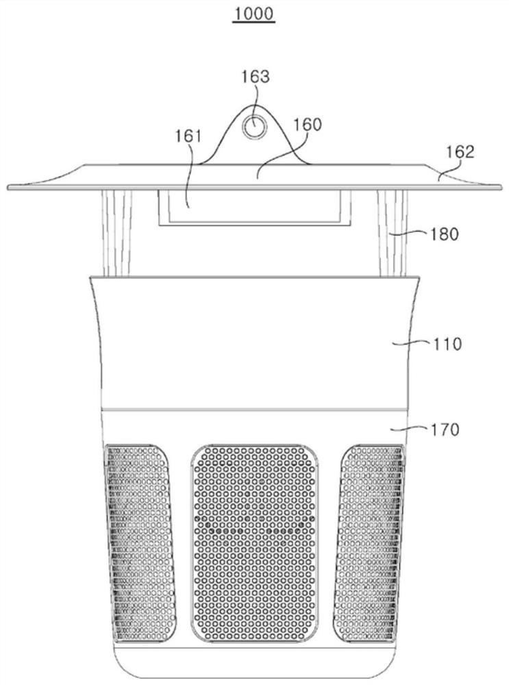
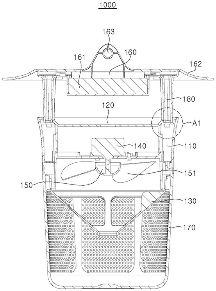
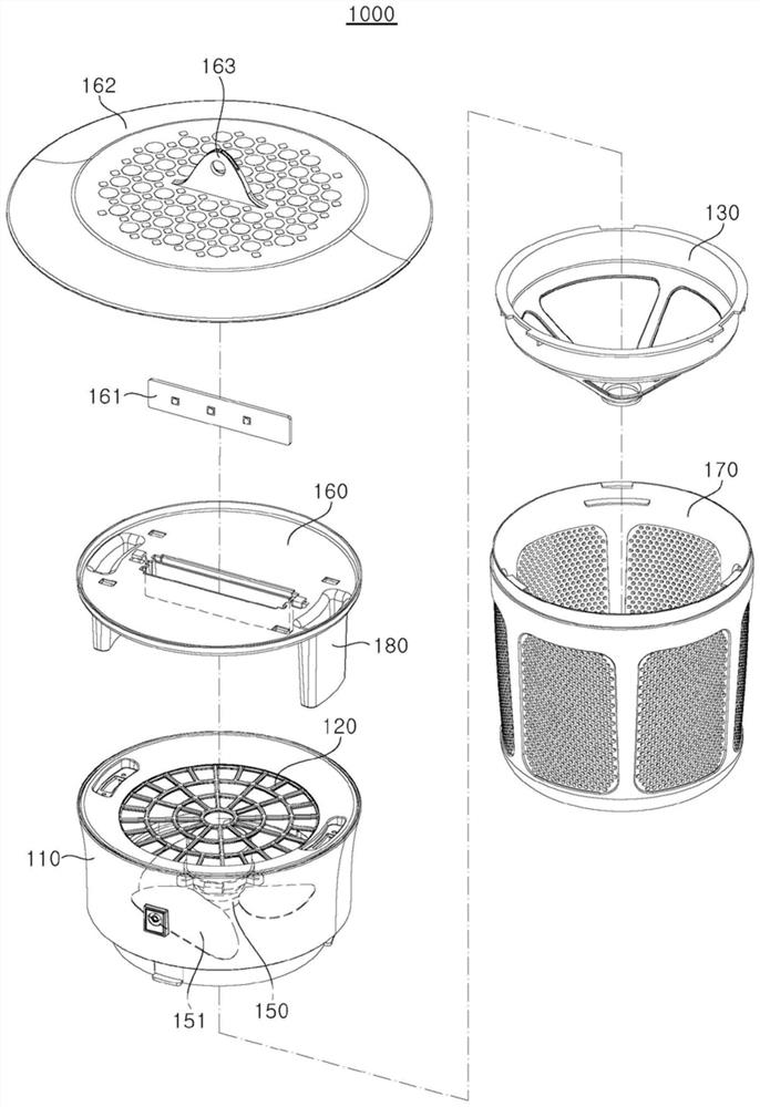
[0095] figure 1 is a side view illustrating an insect trap of one embodiment of the present invention, figure 2 is a sectional view showing an insect trap according to an embodiment of the present invention, image 3 It is an exploded perspective view illustrating an insect trap according to an embodiment of the present invention.

[0096] Refer below Figure 1 to Figure 3 , to describe in detail the components of the insect trap 1000 according to one embodiment of the present invention.

[0097] Insect trap 1000 of one embodiment of the present invention can comprise: main body 110; Insect passage part 120, is arranged on main body 110 and allows insect to pass through in order to utilize ultraviolet ray to lure and catch insects; Motor 140, is positioned at insect passage part 120 bottom; Suction fan 150 is located at the bottom of the motor 140 and rotates by means of the motor 140; the UV LED installation part 160 is in the form of a plate and is arranged on the upper ...

no. 2 example

[0164] The second embodiment of the insect trap 2000 (not shown in the figure) of the present invention can borrow the structure of the first embodiment except that the photocatalytic filter part is installed. The structure of the photocatalytic filter part is described in detail below.

[0165] The photocatalytic filter part may generate carbon dioxide in addition to performing a deodorizing function using UV irradiated by the UV LED module 161 as a catalyst. The installation position of the photocatalytic filter part is not particularly limited as long as the UV generated by the UVLED module 161 in the insect trap 2000 can be irradiated, and it can be installed on the main body 110, the insect passage part 120, the air dust collection part 130, the UV LED Among the installation part 160 , the UV LED installation part canopy 162 , the bracket 180 and the like, preferably, they can be installed under the UV LED installation part 160 and / or the UV LED installation part canopy 16...

manufacture example 1

[0175] refer to image 3 , the vertical height of the main body 110 was 54mm, the vertical height of the catching part 170 was 110mm, the vertical height of the two brackets 180 opposite to each other was 35mm, and the total height of the insect trap was 199mm. In addition, the diameter of the main body 110 and the UV LED mounting part 160 is 133.5 mm, the diameter of the UV LED mounting part canopy 162 is 200 mm, and the maximum height difference between the UV LED mounting part and the UV LED mounting part canopy is 8 mm. , The total area of ​​the insects through the hole 121 is 4882.1mm 2 , The total area of ​​the mesh hole 173 is 9269.3mm 2 , so that the area of ​​an insect passing through the hole 121 is 100mm 2 to 225mm 2 Inside, mosquitoes are selectively passed such that insects larger than mosquitoes are filtered at the insect passing portion 120 .

[0176] In addition, the diameter of the suction fan 150 is 90 mm, the number of blades 151 is three, the height dif...


PUM


Abstract

The present invention provides an insect trap, which uses ultraviolet rays to lure and catch insects, comprising: a main body; an insect passage part arranged on the main body to allow insects to pass through; a motor located under the insect passage part; a suction fan located under the motor , to rotate with the help of a motor; the UV LED installation part is in the form of a plate, which is arranged on the upper part of the insect passage part for the UV LED module to be installed; the bracket separates the UV LED installation part from the main body and supports it on the main body, so that the insects can flow in The space between the main body and the UV LED installation part; the catching part is arranged at the lower part of the main body to catch insects.

Description

technical field [0001] The present invention relates to an insect trap, and more specifically, to an insect trap that absorbs and catches insects attracted by light-attracting light into an airflow formed by means of a suction fan. Background technique [0002] Recently, pests are increasing due to climatic influences such as global warming and environmental protection policies, and social influences. Pests not only harm crops and livestock, but also carry pathogenic bacteria such as malaria, dengue fever, and Japanese encephalitis, which can also cause adverse effects on humans. Especially recently, due to the fearful spread of Zika virus (ZIKV) infection, research on methods related to killing mosquitoes has become more active. [0003] As for the insecticide method, in the past, the chemical control method using insecticides, the biological control method using loach, etc., the physical control method of attracting pests with mosquito lamps and carbon dioxide, etc., and ...

Claims


Application Information

Patent Timeline
Patent Type & Authority Patents(China)
IPC IPC(8): A01M1/02A01M1/08H05B44/00
CPCA01M1/023A01M1/08Y02A50/30A01M1/10A01M2200/01F21V33/008F21W2131/109A01M1/06
Inventor 严勋植
Owner SEOUL VIOSYS CO LTD
Why Eureka
Try Eureka