Multi-stage size beating device for textile size

A textile pulp, multi-stage technology, applied in the direction of grain processing, etc., can solve the problems of poor connection, insufficient beating of pulp, and inability to fully play twice broken, etc., to achieve simple structure, good realization effect, The effect of improving the fineness

Inactive Publication Date: 2017-09-22
SUZHOU RUIRI TEXTILE SCI & TECH
View PDF1 Cites 8 Cited by
  • Summary
  • Abstract
  • Description
  • Claims
  • Application Information

AI Technical Summary

Problems solved by technology

[0004] The purpose of the present invention is to address the deficiencies of the prior art, by setting a crushing mechanism and a cross-cutting mechanism to achieve secondary crushing of the slurry, and by setting a device for controlling the downward flow of the slurr

Method used


Image

  • Multi-stage size beating device for textile size
  • Multi-stage size beating device for textile size
  • Multi-stage size beating device for textile size

Examples


Embodiment 1

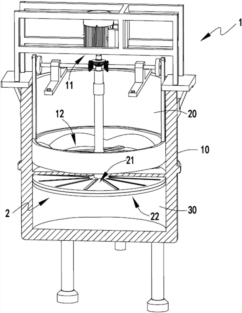
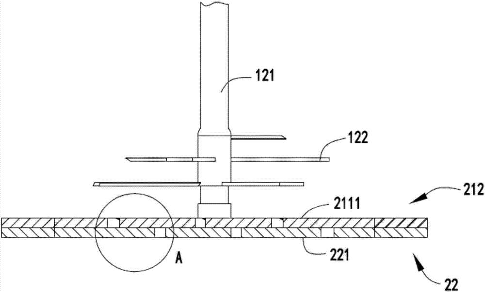
[0042] figure 1 Schematic diagram of the internal structure of the textile pulp multi-stage beating equipment, figure 2 The structure diagram of the crushing mechanism and the toggle device, image 3 Part of the structure diagram when the textile pulp multi-stage beating equipment is closed, Figure 4 Part of the structure diagram when the textile pulp multi-stage beating equipment is opened, Figure 5 It is a schematic diagram of the enlarged structure when the crosscutting device is closed, Image 6 Is the enlarged structure diagram when the crosscutting device is opened, Figure 7 Is the structural diagram of the crosscutting mechanism, Figure 8 Is an enlarged schematic diagram of the arc waist groove, Picture 9 Is the structural diagram of the toggle, Picture 10 Is the structural diagram of the transmission assembly b, Picture 11 Is the structure diagram of the crushing mechanism, Picture 12 Is the structure diagram of the blanking device, Figure 13 It is a schematic di...

Embodiment 2

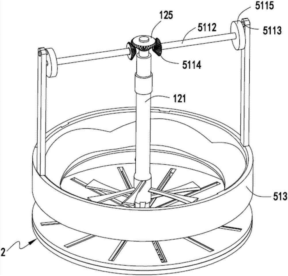
[0056] Such as figure 1 , figure 2 , image 3 , Figure 4 , Figure 5 , Image 6 , Figure 7 , Figure 8 , Picture 9 , Picture 10 , Picture 11 , Picture 12 with Figure 13 As shown, the components that are the same as or corresponding to those in the first embodiment adopt the reference numerals corresponding to the first embodiment. For the sake of simplicity, only the differences from the first embodiment are described below. The second embodiment is different from the first embodiment in that it also includes a toggle mechanism 5 arranged on the side of the crushing mechanism 12, and the toggle mechanism 5 includes a mechanism for transferring the slurry on the inner side of the beating bucket 10 to The middle dialing device 51 includes a transmission assembly a511 and a transmission assembly b512, and a dial 513 fixedly connected to the ends of the transmission assembly a511 and the transmission assembly b512.

[0057] Further, the agitating shaft 121 is provided with be...


PUM


Abstract

The invention relates to a multi-stage beating equipment for textile pulp, which includes a crushing part, the crushing part includes a power mechanism and a crushing mechanism for crushing the pulp in the beating barrel driven by the power mechanism; the cross-cutting part, The cross-cutting part is arranged below the crushing part, and the cross-cutting part includes a cross-cutting mechanism and a control mechanism arranged under the cross-cutting mechanism, and the cross-cutting mechanism divides the beating bucket into primary pulp from top to bottom. The material area and the qualified pulp area, the control mechanism is used to control the slurry in the primary pulp area to flow to the qualified pulp area, and the cross-cutting mechanism is used to control the slurry flowing from the primary pulp area to the qualified pulp area Chopping; the present invention overcomes the problems of insufficient beating of the slurry and inability to connect well between the two beating processes before and after, and cannot give full play to the effects of the two beating processes.

Description

Technical field [0001] The invention relates to the technical field of textile pulping equipment, in particular to a textile pulp multi-stage pulping equipment. Background technique [0002] The textile industry is a traditional industry in China, and it is also a pillar industry related to China’s national economy and people’s livelihood. In traditional pulping and papermaking, after washing, bleaching and purification, the unbeaten pulp contains many fiber bundles. The fibers are too thick and too thick. Long, smooth, stiff and elastic surface, small specific surface area of ​​the fiber and lack of bonding. For example, unbeaten pulp is directly used for papermaking, it is difficult to obtain uniform distribution on the net, the paper is loose and porous, and the surface is rough and easy to fluff. The bonding strength is very low and the paper performance is poor, so it cannot meet the requirements of use. [0003] Authorized announcement number CN204434948 U is a Chinese utili...

Claims


Application Information

Patent Timeline
IPC IPC(8): B02C18/08B02C18/10B02C18/16B02C18/18B02C18/24
CPCB02C18/10B02C18/083B02C18/16B02C18/18B02C18/24
Inventor 施徐哲
Owner SUZHOU RUIRI TEXTILE SCI & TECH
Why Eureka
Try Eureka