Magnet device, magnetic separator and application

A technology of magnets and main magnets, applied in the direction of magnetic separation, solid separation, chemical instruments and methods, etc., can solve the problems of uneven magnetic field force and magnetic field intensity of permanent magnet magnetic separators, and achieve the effect of improving the grade

Active Publication Date: 2017-09-22
张弦
View PDF6 Cites 1 Cited by
  • Summary
  • Abstract
  • Description
  • Claims
  • Application Information

AI Technical Summary

Problems solved by technology

[0004] The present invention is to solve the problem of non-uniform magnetic field force and magnetic field strength of the existing permanent magnet magne

Method used


Image

  • Magnet device, magnetic separator and application
  • Magnet device, magnetic separator and application
  • Magnet device, magnetic separator and application

Examples


Embodiment 1

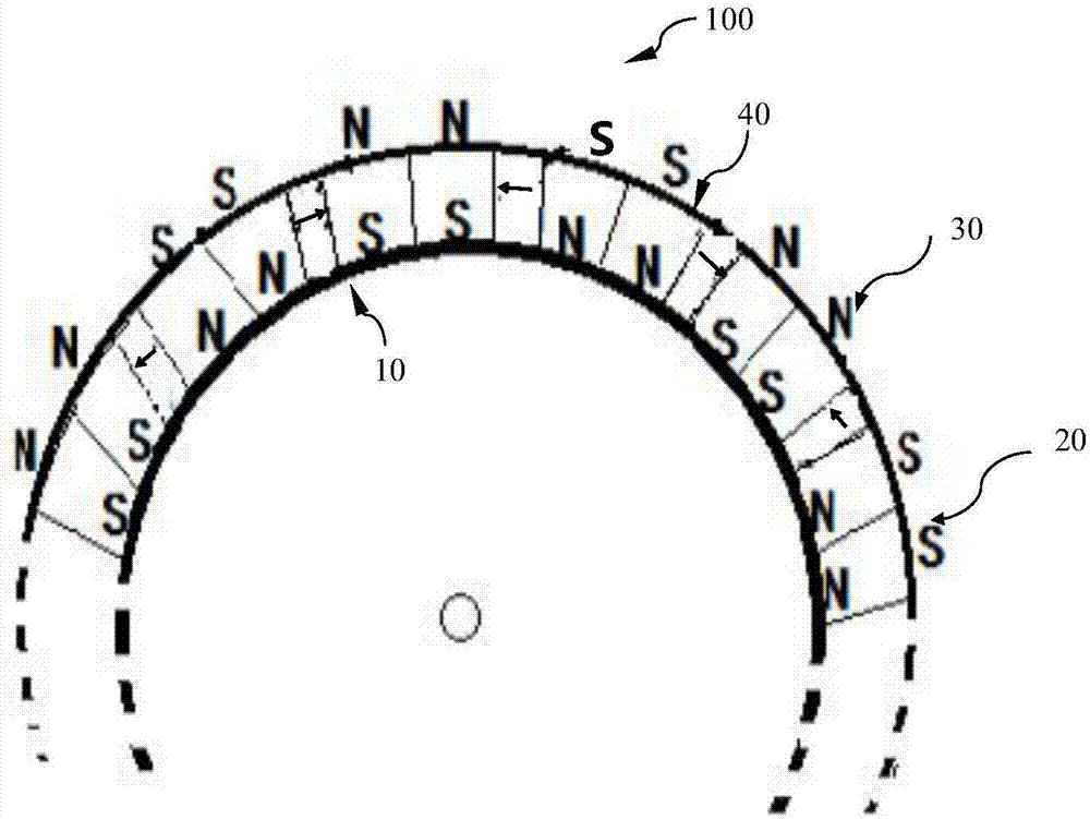
[0026] figure 1 It is a side view of the magnet device in the drum magnetic separator of the present invention.

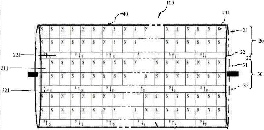
[0027] figure 2 It is a front view of the magnet device in the drum magnetic separator of the present invention.

[0028] This embodiment takes the drum type magnetic separator as an example, as figure 1 , 2 As shown, the drum magnetic separator includes a cylindrical magnet device 100 , a supporting shaft supporting the cylindrical magnet device 100 and a corresponding driving device (not shown in the figure). The ore slurry flows through the magnet device 100 , contacts and rolls on the outer surface of the magnet device 10 driven by the drive device, and completes magnetic separation to obtain concentrate.

[0029] Such as figure 1 As shown, the magnet device 100 includes a cylindrical magnetic permeable layer 10 , a magnet layer composed of a plurality of first magnet parts 20 and a plurality of second magnet parts 30 , and a protective layer 40 .

[003...

Embodiment 2

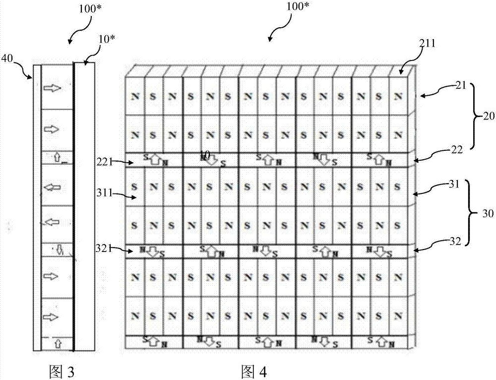
[0063] image 3 It is a side view of the magnet device in the plate magnetic separator of the present invention.

[0064] Figure 4 It is a front view of the magnet device in the plate magnetic separator of the present invention, with the protective layer removed.

[0065] The above embodiment provides a drum-type magnetic separator, and this modified example provides a plate-type magnetic separator 100*, and the magnetically conductive layer of the corresponding magnet device is a rectangular magnetically conductive plate 10*. In this embodiment, the same structures as those in Embodiment 1 are given the same numbers, the first direction is the longitudinal direction of the magnetically conductive plate, and the second direction is the transverse direction of the magnetically conductive plate.

[0066] This plate type magnetic separator can not only be used for magnetic separation, but also suitable for removing iron or other strong magnetic impurities from non-magnetic min...


PUM

PropertyMeasurementUnit
Lengthaaaaaaaaaa
Widthaaaaaaaaaa
Heightaaaaaaaaaa

Abstract

A magnet device comprises a magnetic conductive layer and a magnet layer, wherein the magnet layer is attached to the surface of the magnetic conductive layer and composed of a plurality of first magnet parts and a plurality of second magnet parts; each first magnet part comprises first main magnet units and a first auxiliary magnet unit; each first main magnet unit is formed by arranging first main magnet blocks in the second direction perpendicular to the first direction, and the polarities of every two adjacent magnetic poles of the first main magnet blocks are opposite; each first auxiliary magnet unit is formed by arranging first auxiliary magnet blocks in the second direction in the mode that the polarities of every two adjacent magnetic poles of the first auxiliary magnet blocks are opposite; each second magnet part comprises second main magnet units and a second auxiliary magnet unit; the magnetization direction of the first main magnet blocks and the magnetization direction of second main magnet blocks are parallel, and the magnetization direction of the first auxiliary magnet blocks and the magnetization direction of second auxiliary magnet blocks are perpendicular to the magnetization direction of the first main magnet blocks and the magnetization direction of the second main magnet blocks; and according to the arranging sequence in the second direction, the polarities of the magnetic poles of the first main magnet blocks and the second main magnet blocks in the same serial number are opposite, and the polarities of the magnetic poles of the first auxiliary magnet blocks and the second auxiliary magnet blocks in the same serial number are opposite.

Description

technical field [0001] The invention relates to ore dressing, in particular to the field of magnetic beneficiation, in particular to a device for magnetic beneficiation. Background technique [0002] The current separation of weakly magnetic minerals using permanent magnet technology generally requires the magnetic field strength H of the magnetic pole surface 0 =480~1600kA / m or magnetic field gradient HgradH=(128~576)×10 9 A 2 / m3. Due to the limitations of the existing magnetic material preparation technology, the magnetic energy product of permanent magnetic materials is limited, and it is difficult to meet the magnetic field strength or magnetic force requirements for sorting weak magnetic minerals. Therefore, in actual production, most of them use high energy consumption and are prone to magnetic blockage , Electromagnetic magnetic separator with complex structure. [0003] There are permanent magnetic separators developed by a few companies on the market for sortin...

Claims


Application Information

Patent Timeline
IPC IPC(8): B03C1/02B03C1/12
CPCB03C1/02B03C1/12
Inventor 张弦
Owner 张弦
Why Eureka
Try Eureka