Pipeline cleaning system for grouting equipment of shield machine

A cleaning system and shield machine technology, which is applied in the field of shield machine grouting equipment pipeline cleaning system, can solve the problems of short solidification time, shield construction shutdown, shield construction shutdown loss, etc.

Pending Publication Date: 2017-09-22
BEIJING NO 4 MUNICIPAL CONSTR ENG
View PDF8 Cites 4 Cited by
  • Summary
  • Abstract
  • Description
  • Claims
  • Application Information

AI Technical Summary

Problems solved by technology

Due to engineering needs, the fluidity and plasticity of the grout are generally weak, and the solidification time is relatively short, while the distance from the pump to the shield tail for a single grouting pipeline is relatively long, so the grout often solidifies during the construction process and blocks the tank mouth or pipelines, resulting in shield construction downtime
Therefore, cleaning the grouting equipment is a necessary operation process. The traditional cleaning method is to rinse with a large amount of water, but the flushing effect is not good, and a large amount of waste water is generated. After the pipeline is blocked, it must be disassembled in sections and rinsed with water pipes.
This method is time-consuming and labor-intensive, and causes downtime losses to the shield construction.

Method used


Image

  • Pipeline cleaning system for grouting equipment of shield machine
  • Pipeline cleaning system for grouting equipment of shield machine

Examples


Embodiment 1

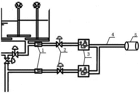
[0017] A check valve 1 , a solenoid valve 2 , a pressure reducing valve 3 and an air compressor 5 are connected sequentially through an air pipe 4 at the mouth of the slurry storage tank or the connection of the pipeline for liquid circulation. Wherein the gas outlet of the one-way valve is connected with the mouth of the slurry storage tank or the slurry circulation pipeline through the gas pipe. When working, the air compressor 5 sends compressed air to the pressure reducing valve 3 through the air pipe 4, and the air decompressed by the pressure reducing valve 3 enters the solenoid valve 2, and then blows into the mouth of the liquid tank or the interface of the pipeline through the check valve 1 , Play a role in preventing the clogging of the tank mouth.

[0018] Preferably, the solenoid valve is an eardrum solenoid valve.

[0019] Further, a control system can be set to control the start and stop of related operations, the control system is connected with the operating s...

Embodiment 2

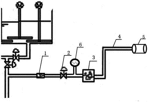
[0022] In the operating system of the grouting pipeline cleaning system in this embodiment, the air compressor 5 is connected to the pressure reducing valve 3 through the air pipe 4, the pulse meter 6 and the pressure reducing valve 3 are connected in parallel to the solenoid valve 2 through the air pipe 4, and the solenoid valve 2 passes through The air pipe 4 is connected to the one-way valve 1, and the water outlet of the one-way valve 1 is connected with the slurry circulation pipeline through the air pipe. The operating system of this embodiment is similar to the working principle of the operating system of Embodiment 1, the difference is that the alternate operation of water and air is controlled by the pulse instrument 6, which will cause air explosion in the pipeline and reduce the formation of liquid A hanging on the wall. The pipe of this method Road cleaning is cleaner than single-water cleaning, and it saves more water than single-water cleaning of pipelines.

[00...


PUM


Abstract

The invention provides a pipeline cleaning system for grouting equipment of a shield machine. The pipeline cleaning system comprises a control system and an operation system, wherein the operation system is composed of one-way valves, electromagnetic valves, pressure reducing valves, an air pipe, an air compressor and the like. According to the pipeline cleaning system, after the pressure of compressed air is manually regulated through the pressure reducing valves, the compressed air passes through the tympanic membrane electromagnetic valves, enters the one-way valves and is blown into a stirring tank so as to prevent a tank opening from being blocked, or the pipeline is subjected to pulse washing by means of alternate working of water and air, and therefore the phenomenon that the construction progress is delayed due to blockage of the tank opening in the construction process can be avoided, and the continuity and the efficiency of construction can be guaranteed.

Description

technical field [0001] The invention relates to the technical field of shield tunneling construction, in particular to a pipeline cleaning system for shield tunneling machine grouting equipment. Background technique [0002] As a special engineering machinery and high-tech construction equipment for tunneling, the shield machine integrates optoelectronics, machinery, sensing and information technology, and is widely used in urban rail transit, railway, highway, municipal, hydropower and other tunnel projects. [0003] During the construction process, after the shield machine is excavated, in order to control the deformation of the ground, improve the impermeability of the tunnel and the early stability of the segment lining, it is necessary to fill the grout in the circumferential direction behind the segment wall by synchronous grouting. Synchronous grouting is an essential operation link in shield tunneling construction, and its grouting effect directly affects the waterpr...

Claims


Application Information

Patent Timeline
Patent Type & Authority Applications(China)
IPC IPC(8): B08B9/032
CPCB08B9/0321B08B9/0326B08B9/0328
Inventor 刁春仁耿富林郑林有刘振丹周政聂晓彦刘德英王航飞许建安
Owner BEIJING NO 4 MUNICIPAL CONSTR ENG
Why Eureka
Try Eureka