
Waste tire recycling device

A waste tire and recycling device technology, applied in recycling technology, combined device, plastic recycling, etc., can solve problems such as only emission to the sky, unenvironmental protection, secondary pollution, etc., and achieve good recycling and good environmental performance.

Inactive Publication Date: 2017-09-22
WUHAN UNIV OF SCI & TECH
View PDF0 Cites 0 Cited by
  • Summary
  • Abstract
  • Description
  • Claims
  • Application Information

AI Technical Summary

Problems solved by technology

[0002] With the continuous development of the environmental protection industry, the practical application of environmental protection treatment has become increasingly commercialized, and the development of recycled resource utilization of waste plastics, tires, and waste engine oil has also become mature. However, most of these projects are currently in the single use and development. There is no comprehensive consideration of the recycling of the remaining products in the recycling process
For example, taking a single waste plastic and tire refining equipment as an example, most of the equipment basically did not consider the real environmental protection treatment of exhaust gas, nor did it consider the issue of hot gas recovery and reuse. more downplaying or simply ignoring
The combustible gas (non-toxic gas) produced in waste plastics and tire oil refining is only returned to the furnace for combustion, but in actual production, the time of gas generation and the burning time of the cracking furnace are two concepts. During this period of completion, only two-thirds of the gas will be burned back, and the remaining combustible gas can only be discharged to the sky. The environmental protection recycling equipment mentioned above is actually not environmentally friendly, and may cause secondary pollution problems , At the same time, it is indeed a defect to waste a large amount of reusable resources with economic value

Method used


Image

  • Waste tire recycling device
  • Waste tire recycling device

Examples


Embodiment Construction

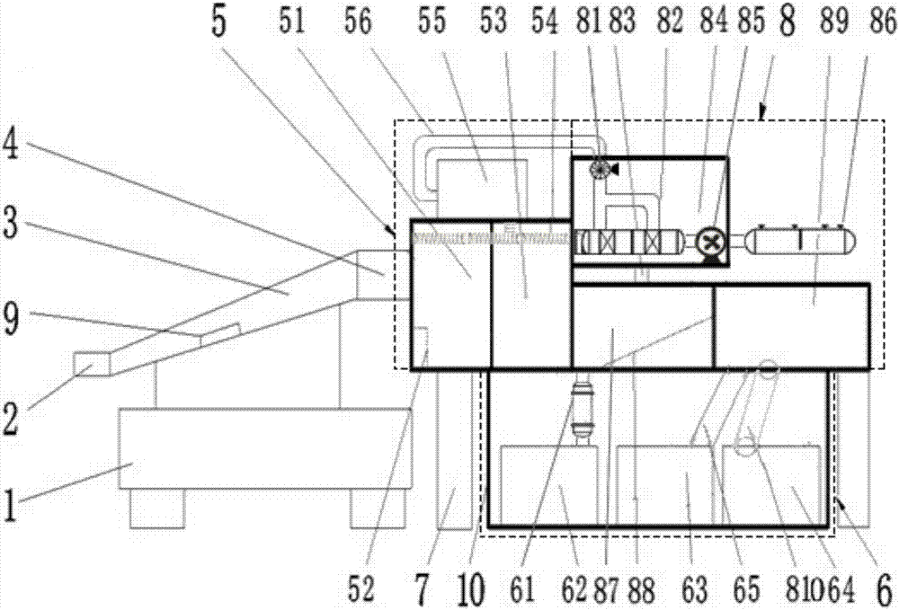
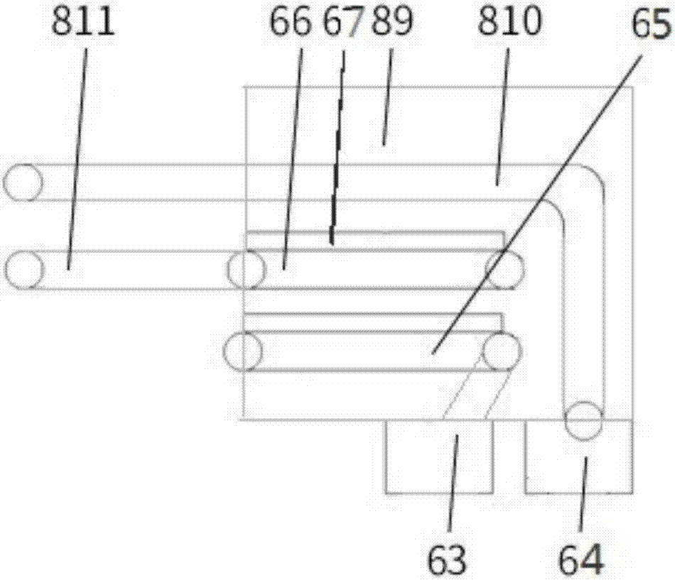
[0019] Below by embodiment, in conjunction with accompanying drawing, the technical scheme of the present invention is described further specifically, as Figure 1-2 As shown, a waste tire recovery and recycling device includes a base 1 and a support frame 7, the base 1 is provided with a conveying device 3, and the support frame 7 is provided with a pyrolysis reaction device 5 and a discharge Device 8, a recovery device 6 is provided inside the support frame 7, and it is characterized in that: the head and tail of the conveying device 3 are respectively connected to the feed port 2 and the discharge port 4, and the discharge port 4 is connected to the pyrolysis reaction device 5, and the One side of the pyrolysis reaction device 5 is docked with the discharge port 4, and the other side is provided with a discharge device 8, and the recovery device 6 is arranged below the pyrolysis reaction device 5 and the discharge device 8.

[0020] Described pyrolysis reaction device 5 com...


PUM


Abstract

The invention provides a waste tire recycling device. The waste tire recycling device comprises a base and a support frame, wherein the base is provided with a conveying device; the support frame is provided with a pyrolytic reaction device and a discharging device; a recycling device is arranged inside the support frame; the head and the tail of the conveying device are connected with a charging hole and a discharging hole respectively; the discharging hole is connected with the pyrolytic reaction device; one side of pyrolytic reaction device is in butt joint with the discharging hole; the other side of pyrolytic reaction device is provided with the discharging device; the recycling device is arranged below the pyrolytic reaction device and the discharging device. The waste tire recycling device is simple in structure, is safe and convenient to use, and has a reasonable regeneration system. By adopting the waste tire recycling device, the influence on an external environment can be lowered effectively, the implementation of environmental policies is ensured, the oil producing rate and the recycling rates of activated carbon and steel wires can be increased effectively, the labor strength of operators is lowered effectively, and the working efficiency is increased.

Description

technical field [0001] The invention belongs to the field of recycling machinery, and in particular relates to a recycling device for recycling waste tires. Background technique [0002] With the continuous development of the environmental protection industry, the practical application of environmental protection treatment has become increasingly commercialized, and the development of recycled resource utilization of waste plastics, tires, and waste engine oil has also become mature. However, most of these projects are currently in the single use and development. There is no comprehensive consideration of the recycling of the remaining products in the recycling process. For example, taking a single waste plastic and tire refining equipment as an example, most of the equipment basically did not consider the real environmental protection treatment of exhaust gas, nor did it consider the issue of hot gas recovery and reuse. More understatement or simply ignore. The combustibl...

Claims


Application Information

Patent Timeline
IPC IPC(8): C10G1/10B01J6/00C09C1/48C08J11/12B01D50/00B01D53/50B01D53/60B01D53/75B01D53/78
CPCB01D53/502B01D53/60B01D53/75B01D53/78B01J6/008C10G1/10C08J11/12C09C1/482C09C1/487C10G2300/1003B01D50/60Y02W30/62
Inventor 孟巧丽王菊梅程亦婷陈玉婷
Owner WUHAN UNIV OF SCI & TECH
Learn More