Shield segment and application of shield segment to shield tunneling machine passing through mined tunnel in empty push mode

A technology of shield segment and mining method, which is applied in the direction of tunnels, tunnel linings, mining equipment, etc., can solve the problems of easy opening of segment joints, inability to provide compacting force for tunnel structure, low construction efficiency, etc., and achieve reduction The effect of a small error

Pending Publication Date: 2017-09-22
CHINA RAILWAY SIYUAN SURVEY & DESIGN GRP
View PDF8 Cites 16 Cited by
  • Summary
  • Abstract
  • Description
  • Claims
  • Application Information

AI Technical Summary

Problems solved by technology

The three-stage filling method of bean gravel spraying, synchronous grouting and ground hole grouting is adopted. The bean gravel transportation, screw conveyor loading and dry jetting are all mechanically constructed, which solves the defect of low construction efficiency in the existing construction methods and is widely used. Suitable for tunnel construction using mining method + shield construction method
[0004] However, the above solution cannot provide effective compaction force to the tunnel structure due to the combination of pea gravel and segment grouting, resulting in the joints

Method used


Image

  • Shield segment and application of shield segment to shield tunneling machine passing through mined tunnel in empty push mode
  • Shield segment and application of shield segment to shield tunneling machine passing through mined tunnel in empty push mode
  • Shield segment and application of shield segment to shield tunneling machine passing through mined tunnel in empty push mode

Examples


Example Embodiment

[0033] In order to make the objectives, technical solutions and advantages of the present invention clearer, the following further describes the present invention in detail with reference to the accompanying drawings and embodiments. It should be understood that the specific embodiments described herein are only used to explain the present invention, but not to limit the present invention.

[0034] In addition, the technical features involved in the various embodiments of the present invention described below can be combined with each other as long as they do not conflict with each other.

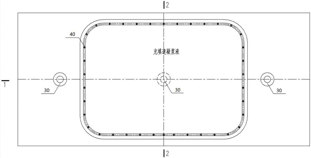
[0035] Such as Figure 2 to Figure 7 As shown, the shield segment 10 of the embodiment of the present invention includes a segment body, and a plurality of grouting holes are embedded in the segment body for providing grouting channels, which respectively penetrate the segment body, preferably a tube Three or more grouting holes are pre-buried on the sheet body. Wherein, at least one grouting ...


PUM


Abstract

The invention discloses a shield segment which comprises a segment body, a plurality of injected holes formed in the segment body in a pre-buried mode and used for supplying grouting channels and grouting bags arranged on the outer side of the outer wall surface of the segment body and used for being filled with grouting slurry so that after the grouting slurry is solidified, the gap between the segment body and a primary support can be filled to form effective support for the segment body; and after a shield tunneling machine passes through a mined tunnel section, gaps among all the grouting bags on the outer side of the segment body are filled through slurry injection into the injected holes, so that the interiors and exteriors of the grouting bags on the outer side of the segment body are densely filled with the slurry to form a water-insulating layer. The invention further discloses a construction method of the shield segment for a shield tunneling machine passing through a mined tunnel in an empty push mode. The grouting bags are arranged on the outer side of the segment body, so that the quick setting slurry is injected into the grouting bags during assembly to fill the gap between the primary support and a segment structure; and the injected holes are additionally formed in the segment structure, through the injected holes, the gaps between the grouting bags behind the segment wall are filled, and dense filling of the slurry behind the segment wall is ensured to form the effective water-insulating layer.

Description

technical field [0001] The invention belongs to the technical field of shield tunnel construction, and in particular relates to a shield segment and the application of the shield tunnel through a mine tunnel. Background technique [0002] In recent years, the shield tunneling method has been widely used in railway, highway, municipal and other industries. When the shield machine partially passes through hard rock, boulder groups, or the upper soft and lower hard sections, it often uses the mining method to excavate first, and the shield machine then pushes through the method. [0003] Traditional shield tunneling is to spray pea gravel from the front of the cutter head (or segment grouting hole) to fill the gap between the segment and the initial support of the tunnel when the shield is advancing, and then grout from the segment grouting hole or directly behind the wall. Synchronous grouting is stable. For example, the patent document CN102425427A discloses a method and de...

Claims


Application Information

Patent Timeline
IPC IPC(8): E21D11/08E21D11/10E21D9/06
CPCE21D9/0607E21D11/08E21D11/105Y02E10/20
Inventor 肖明清邓朝辉薛光桥孙峰
Owner CHINA RAILWAY SIYUAN SURVEY & DESIGN GRP
Why Eureka
Try Eureka