
Shield tunnel segment assembling positioning device and shield tunnel segment assembling process

A shield tunnel segment and positioning device technology, which is applied in tunnels, tunnel linings, optical device exploration, etc., can solve the hidden dangers of long-term structural safety and operation and maintenance of tunnels, cracking of concave and convex tenon concrete of segments, and difficulty in ensuring assembly quality and other problems, to achieve the effect of improving assembly quality and assembly efficiency, low construction process requirements, and convenient observation

Pending Publication Date: 2020-12-04
POWERCHINA RAILWAY CONSTR +2
View PDF0 Cites 0 Cited by
  • Summary
  • Abstract
  • Description
  • Claims
  • Application Information

AI Technical Summary

Problems solved by technology

This operation judges and adjusts the position of the segment through the naked eye observation of the staff, which has high requirements on the staff and is prone to errors; the adjustment process requires the coordination and cooperation of the staff and continuous adjustment, which is usually difficult to achieve fast and efficient assembly, and it is difficult to ensure good quality. Excellent assembly quality, laying hidden dangers for the long-term structural safety and operation and maintenance of the tunnel
In order to improve the assembly accuracy of segments, some projects adopt the method of setting concave and convex tenons in the design. This method can effectively improve the assembly quality of segment lining, but the accuracy of segment assembly is higher, and improper control can easily lead to segment failure. Concave and tenon and its surrounding concrete cracks

Method used


Image

  • Shield tunnel segment assembling positioning device and shield tunnel segment assembling process
  • Shield tunnel segment assembling positioning device and shield tunnel segment assembling process
  • Shield tunnel segment assembling positioning device and shield tunnel segment assembling process

Examples


Embodiment

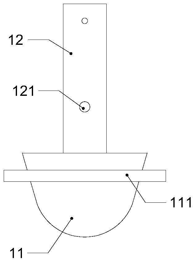
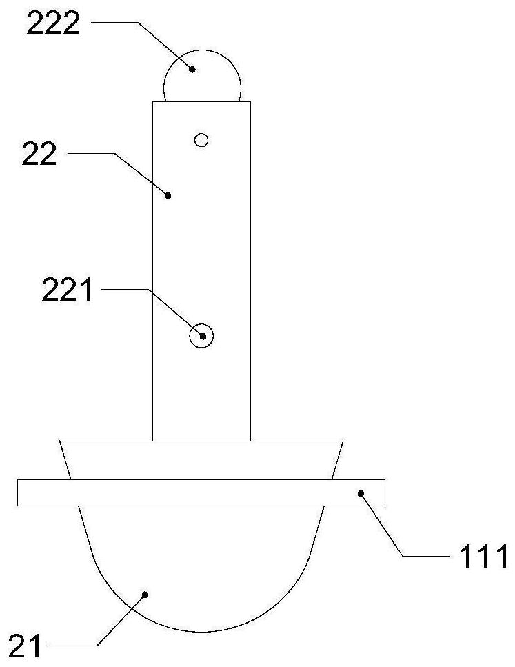
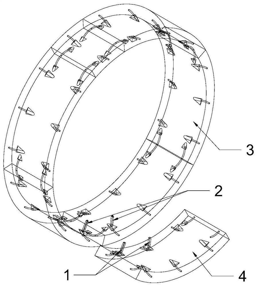
[0039] refer to figure 1 and figure 2, a segment assembly and positioning device for a shield tunnel, including: a laser emitting part 1 and a laser receiving part 2 paired with the laser emitting part 1, the laser emitting part 1 includes: a first fixing support that matches the upper hand hole of the segment The base 11 and the laser emitter 12 arranged on the first fixed support 11, the laser receiver 2 includes: the second fixed support 21 matched with the upper hand hole of the tube sheet and the laser light set on the second fixed support 21 Receiver 22. Before construction, the shield tunnel segment should be designed according to engineering geological and hydrological conditions, tunnel depth, tunnel diameter, construction requirements, etc., and the first fixed support can be further designed according to the hand hole size of the segment. The size of the base and the second fixed support, and the bottom of the laser transmitter 12 and the laser receiver 22 are fix...


PUM


Abstract

The invention discloses a shield tunnel segment assembling positioning device and a shield tunnel segment assembling process, and relates to the technical field of tunnel construction. The assemblingpositioning device comprises a laser emitting piece and a laser receiving piece paired with the laser emitting piece; and the laser emitting piece comprises a first fixing support matched with a handhole in a segment and a laser emitter arranged on the first fixing support. The laser receiving piece comprises a second fixing support matched with a hand hole in the segment and a laser receiver arranged on the second fixing support. The assembling process comprises the steps of installing a first circle of tunnel segments, installing first segments, installing second segments, installing othersegments and installing other circles of tunnel segments, the assembling positioning device and the assembling process can enable the segments to be assembled and the assembled segments to be accurately aligned, slab staggering between segment rings and in the rings can be reduced, the assembling quality of the segments is improved, and the assembling efficiency of the segments can also be improved.

Description

technical field [0001] The invention relates to the technical field of tunnel construction, in particular to a shield tunnel segment assembling and positioning device and an assembling process. Background technique [0002] With the rapid advancement of my country's urbanization process and the explosive growth of urban population, urban ground traffic is becoming more and more congested, which brings inconvenience to people's transportation, life and work, and affects the rapid development of the national economy to a certain extent. . The development of underground railways based on rail transportation has become the first choice for my country to alleviate the pressure of ground transportation and fundamentally solve traffic congestion at this stage. Among many tunnel construction methods, the shield tunneling method has been widely used in tunnel engineering because of its advantages of safe excavation and lining, fast excavation speed, low construction labor intensity, ...

Claims


Application Information

Patent Timeline
Patent Type & Authority Applications(China)
IPC IPC(8): E21D11/08G01V8/20
CPCE21D11/08E21D11/083G01V8/20
Inventor 吴恒生郭伟李鹏飞王亚郭岳雷赵江昊丁延昌任冬生杨旭东王士民
Owner POWERCHINA RAILWAY CONSTR
Learn More