Double-coil piston type magnetorheological fluid damper

A magneto-rheological fluid and piston-type technology, applied in the direction of shock absorbers, shock absorbers, springs/shock absorbers, etc., can solve the problems of swing reduction failure, narrow damping working range, and non-adjustable damping force, etc., and achieve increased The effect of the initial damping force

Active Publication Date: 2017-09-22
CIVIL AVIATION UNIV OF CHINA
View PDF11 Cites 10 Cited by
  • Summary
  • Abstract
  • Description
  • Claims
  • Application Information

AI Technical Summary

Problems solved by technology

The main working principle of the traditional oil-type shock absorber is that the hydraulic oil is squeezed into the throttling device under the push of the piston, and the oil and the throttling device have severe friction to generate a damping force. Different shock absorbers have different damping devices. Therefore, there are poor general purpose, narrow damping working range, and non-adjustable damping force during the working process. In addition, due to the small aperture of the throttling device or the small gap of the damping channel, faults such as blockage or swing reduction failure are prone to occur during long-term use.

Method used


Image

  • Double-coil piston type magnetorheological fluid damper
  • Double-coil piston type magnetorheological fluid damper
  • Double-coil piston type magnetorheological fluid damper

Examples


Embodiment Construction

[0033] The present invention will be described in further detail below through specific examples. The following examples are only descriptive and not restrictive, and the protection scope of the present invention cannot be limited by this.

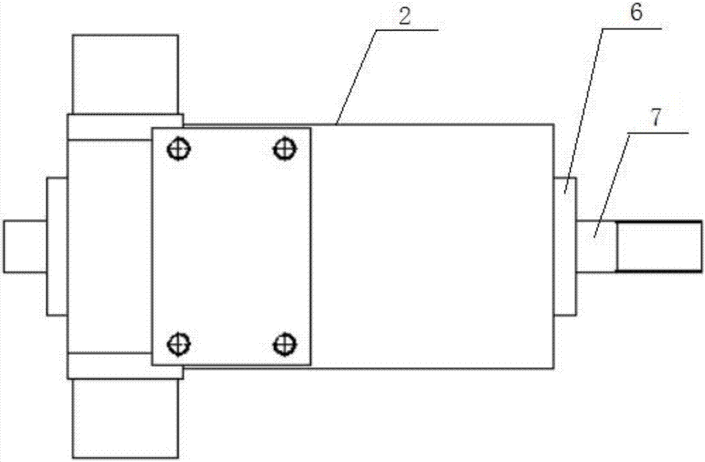
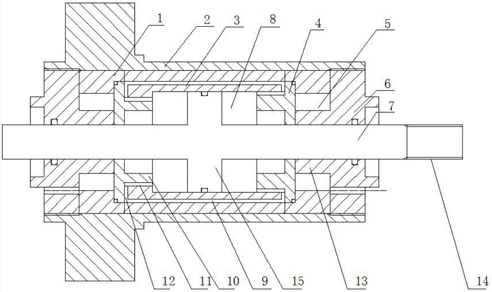
[0034] Such as figure 1 , 2 As shown, a dual-coil piston type magnetorheological fluid damper includes an outer cylinder 2, an inner cylinder 3, an end cover 6, a piston shaft 7, a magnetic permeable ring 1 and a magnetic isolation ring 4. The outer cylinder Both ends of the cylinder are fixed with end covers, and the inner cylinder is coaxially installed in the outer cylinder. Magnetic rings are fixed between both ends of the inner cylinder and the end cover. The magnetic isolation ring is fixed, the two ends of the piston shaft are coaxially inserted into the inner cylinder tube and coaxially slidingly installed with the end cover and the magnetic isolation ring. The piston part 15 of the piston shaft divides the space between the inner cyl...


PUM


Abstract

The invention relates to a double-coil piston type magnetorheological fluid damper. The double-coil piston type magnetorheological fluid damper comprises an outer cylinder barrel, an inner cylinder barrel, end covers, a piston shaft, magnetic guiding loops and magnetic insulating loops. The end covers are fixedly arranged on both ends of the outer cylinder barrel, the inner cylinder barrel is coaxially installed in the outer cylinder barrel, the magnetic guiding loops are fixed between the two ends of the inner cylinder barrel and the end covers, the magnetic insulating loops are fixed between two ends of the inner cylinder barrel and the magnetic guiding loops, and two ends of the piston shaft are coaxially inserted into the inner cylinder barrel and installed with the end covers and the magnetic insulating loops in a sliding mode; a plurality of damping channels are arranged in the inner cylinder barrel in the circumferential direction, and a magnetorheological fluid storage cavity and the damping channels are filled with magnetorheological fluid; and coils are twined around the inner ends of the end covers, and a closed magnetic loop is formed by the magnetic guiding loops, the inner cylinder barrel and the end covers after the coils are electrified and the piston shaft operates. According to the double-coil piston type magnetorheological fluid damper, the damping channels are lengthened under the condition that the piston stroke is satisfied, great initial damping force is generated without loading electric current, great coulomb force is generated after the electric current is loaded, the working scope is expanded, and the adjustable multiple of the damping force of the damper is increased.

Description

Technical field [0001] The invention belongs to the field of aircraft accessories, and relates to an aircraft landing gear, in particular to a dual-coil piston magnetorheological fluid damper. Background technique [0002] Aircraft with front three-point landing gear arrangement has the disadvantage of front landing gear shimmy during taxiing or taxiing. The reason for the front wheel shimmy of the aircraft is: the lateral vibration of the pillar and the front wheel and the front wheel torsion around the axis of the pillar A very complex self-excited vibration caused by the mutual coupling of vibrations. The energy to maintain this self-excited vibration is provided by the force and moment of the ground acting on the tires during the taxiing of the aircraft. In order to solve this problem, the method commonly used in the aviation industry is to arrange an oil-type damper on the nose landing gear. The main working principle of the traditional hydraulic damper is that the hydrauli...

Claims


Application Information

Patent Timeline
Patent Type & Authority Applications(China)
IPC IPC(8): F16F9/53F16F9/32
CPCF16F9/3207F16F9/535
Inventor 祝世兴刘秀魏德功崔荣耀杨正权刘小川豆清波
Owner CIVIL AVIATION UNIV OF CHINA
Why Eureka
Try Eureka