Remote control system for emergency power supply equipment

A remote monitoring system and emergency power supply technology, applied in information technology support systems, electrical components, circuit devices, etc., can solve problems such as high network wiring costs, difficult wireless communication distance, and inability to expand, and achieve safe and reliable signal transmission. Improved convenience and safety, good signal effect

Inactive Publication Date: 2017-09-22
HEFEI LIYUANJIE INFORMATION TECH CO LTD
View PDF1 Cites 0 Cited by
  • Summary
  • Abstract
  • Description
  • Claims
  • Application Information

AI Technical Summary

Problems solved by technology

Among them, the monitoring system using wired communication requires the wiring of the wired communication network, and the cost of network wiring is relatively high. In addition, when the monitoring data signal is transmitted in the communication cable, it is easily affected by environmental interference and causes signal attenuation. For long-distance transmission When monitoring these data, more environmental factors need to be considered; and the wireless power monitoring system using short-range wireless transmission technology (such as Bluetooth, infrared), its transmission distance is often limited to a certain area, when it exceeds a certain range , Bluetooth, infrared and other short-distance signals will be limited
Among them, the distance of Bluetooth transmission generally does not exceed 100 meters, and the distance of infrared transmission is shorter, and the wireless communication distance of these two methods is difficult or impossible to expand

Method used


Image

  • Remote control system for emergency power supply equipment

Examples


Embodiment 1

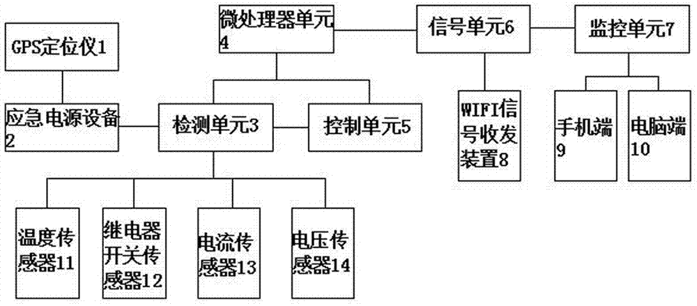
[0024] A remote monitoring system for emergency power supply equipment, including emergency power supply equipment 2, detection unit 3, control unit 5, microprocessor unit 4, signal unit 6 and monitoring unit 7, emergency power supply equipment 2 is connected with detection unit 3, detection unit 3 Connected with the control unit 5, the control detection unit 3 detects the emergency power supply equipment 2, the detection unit 3 and the control unit 5 are also connected with the microprocessor unit 4, the detection unit 3 directly feeds back the detection data to the microprocessor unit 4, and the control unit 5 is composed of The microprocessor unit 4 transmits control instructions, the microprocessor unit 4 is connected to the signal unit 6 , the signal unit 6 is connected to the monitoring unit 7 , and the microprocessor unit 4 receives and feeds back information to the monitoring unit 7 through the signal unit 6 .

[0025] The detection unit 3 is provided with a temperature...

Embodiment 2

[0034] A remote monitoring system for emergency power supply equipment, including emergency power supply equipment 2, detection unit 3, control unit 5, microprocessor unit 4, signal unit 6 and monitoring unit 7, emergency power supply equipment 2 is connected with detection unit 3, detection unit 3 Connected with the control unit 5, the control detection unit 3 detects the emergency power supply equipment 2, the detection unit 3 and the control unit 5 are also connected with the microprocessor unit 4, the detection unit 3 directly feeds back the detection data to the microprocessor unit 4, and the control unit 5 is composed of The microprocessor unit 4 transmits control instructions, the microprocessor unit 4 is connected to the signal unit 6 , the signal unit 6 is connected to the monitoring unit 7 , and the microprocessor unit 4 receives and feeds back information to the monitoring unit 7 through the signal unit 6 .

[0035] The detection unit 3 is provided with a temperature...

Embodiment 3

[0043] A remote monitoring system for emergency power supply equipment, including emergency power supply equipment 2, detection unit 3, control unit 5, microprocessor unit 4, signal unit 6 and monitoring unit 7, emergency power supply equipment 2 is connected with detection unit 3, detection unit 3 Connected with the control unit 5, the control detection unit 3 detects the emergency power supply equipment 2, the detection unit 3 and the control unit 5 are also connected with the microprocessor unit 4, the detection unit 3 directly feeds back the detection data to the microprocessor unit 4, and the control unit 5 is composed of The microprocessor unit 4 transmits control instructions, the microprocessor unit 4 is connected to the signal unit 6 , the signal unit 6 is connected to the monitoring unit 7 , and the microprocessor unit 4 receives and feeds back information to the monitoring unit 7 through the signal unit 6 .

[0044] The detection unit 3 is provided with a temperature...


PUM


Abstract

The invention provides a remote control system for emergency power supply equipment. The remote control system comprises the emergency power supply equipment, a detection unit, a control unit, a microprocessor unit, a signal unit and a monitoring unit, wherein the emergency power supply equipment is connected with the detection unit; the detection unit is connected with the control unit; the detection unit is controlled for detecting the emergency power supply equipment; the detection unit and the control unit are further connected with the microprocessor unit; the detection unit is used for feeding back detection data through the microprocessor unit; the control unit is used for transmitting a control command through the microprocessor unit; the microprocessor is connected with the signal unit; the signal unit is connected with the monitoring unit; and the microprocessor unit is used for receiving and feeding back information to the monitoring unit through the signal unit. According to the remote control system, wireless remote monitoring for the emergency power supply equipment can be realized, so that the convenience and security for monitoring the emergency power supply equipment are improved, the maintenance cost of the emergency power supply equipment is also reduced, and the system is simple in structure and easy to operate.

Description

technical field [0001] The invention belongs to the technical field of power supply equipment, and in particular relates to a remote monitoring system for emergency power supply equipment. Background technique [0002] At present, the commonly used emergency power equipment is installed at a high position or far away from people's living areas, which is often beyond our visual range. However, it is necessary to regularly monitor and understand the operating status of these emergency power equipment during operation. At present, wired communication connection or short-range wireless transmission is generally adopted to learn the operating status of these emergency power supply devices. Among them, the monitoring system using wired communication requires the wiring of wired communication network, and the cost of network wiring is relatively high. In addition, when the monitoring data signal is transmitted in the communication cable, it is easily affected by environmental inter...

Claims


Application Information

Patent Timeline
Patent Type & Authority Applications(China)
IPC IPC(8): H02J13/00
CPCH02J13/0075Y04S40/126Y02E60/00
Inventor 不公告发明人
Owner HEFEI LIYUANJIE INFORMATION TECH CO LTD
Why Eureka
Try Eureka