Hydraulic cavitation generating device and hydraulic cavitation generating method

A generation device, hydraulic cavitation technology, applied in the method of using atmospheric pressure to chemically change substances, chemical instruments and methods, water/sewage treatment, etc., can solve the problem of triggering or intensifying physical and chemical reactions, Solve the problems of large piping structure of the system and small processing capacity of the cavitation reactor to achieve low equipment manufacturing costs, reduce scale and complexity, and reduce input costs

Pending Publication Date: 2017-09-26
RES INST OF PHYSICAL & CHEM ENG OF NUCLEAR IND
View PDF10 Cites 2 Cited by
  • Summary
  • Abstract
  • Description
  • Claims
  • Application Information

AI Technical Summary

Problems solved by technology

[0006] Although the research on hydrodynamic cavitation has gradually deepened, and the number of cavitator structures proposed has increased, the cavitation intensity and efficiency of hydrodynamic cavitation are relatively low, which is often not enough to trigger or intensify certain physical and chemical reactions.
In addition, the processing capacity of the cavitation reactor is small, and multiple devices need to be used in parallel or in series for large-scale processing, resulting in a large and complex pipeline structure of the processing system, which is still difficult to promote and apply industrially

Method used


Image

  • Hydraulic cavitation generating device and hydraulic cavitation generating method
  • Hydraulic cavitation generating device and hydraulic cavitation generating method

Examples


Embodiment Construction

[0034] The present invention will be described in further detail below in conjunction with the accompanying drawings and specific embodiments. It should be understood that the specific embodiments described here are only used to explain the present invention, not to limit the present invention.

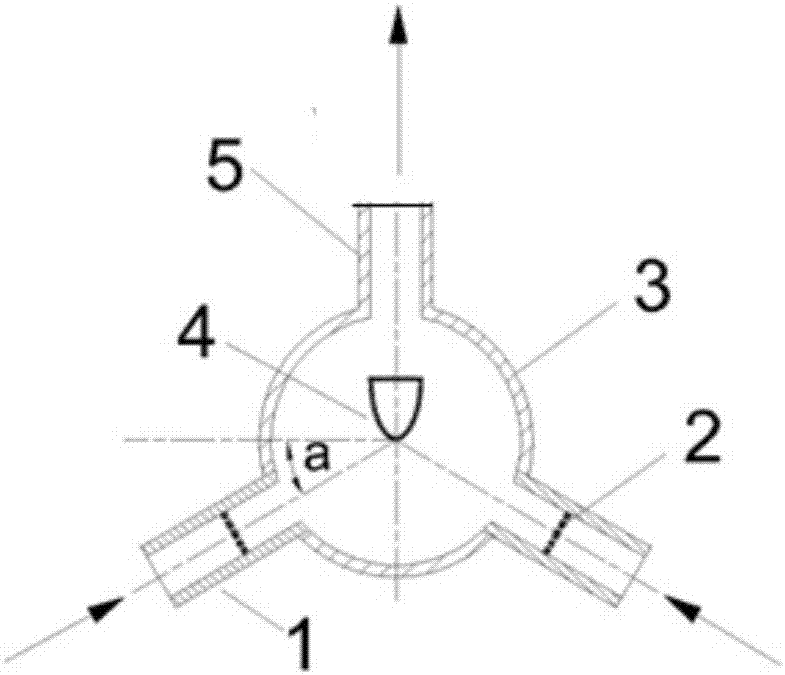
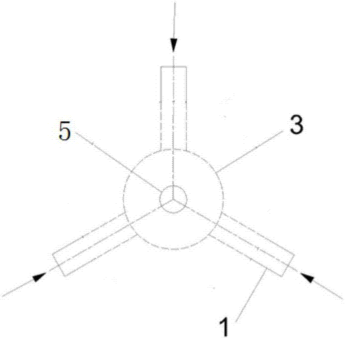
[0035] like Figure 1-2 As shown, a hydraulic cavitation generating device includes a fluid inlet pipe 1, an orifice plate 2, a spherical cavity 3, a cavitation enhancement module 4, a fluid outlet pipe 5, and a plurality of fluid inlet pipes 1 ( figure 1 The middle fluid inlet pipe 1 is provided with two, figure 2 The middle fluid inlet pipe 1 is provided with three) connected with the lower half of the spherical cavity 3, and the axis of each fluid inlet pipe 1 inlet pipe passes through the center of the spherical cavity 3, and all form an angle a (a is 0 degree) with the horizontal direction ~80 degrees), there are at least two fluid inlet pipes 1, which are evenly distributed a...


PUM

PropertyMeasurementUnit
porosityaaaaaaaaaa

Abstract

The invention discloses a hydraulic cavitation generating device and a hydraulic cavitation generating method. The device comprises a spherical chamber and a plurality of fluid inlet pipes, wherein the spherical chamber is internally provided with a spherical cavity; the plurality of fluid inlet pipes are evenly arranged at the lower half part of the spherical chamber and are communicated with the spherical chamber; the axes of all the fluid inlet pipes pass through the center of the spherical chamber, and the included angles formed between the fluid inlet pipes and the horizontal direction are the same as one another; the fluid inlet pipes are respectively and internally provided with an orifice plate; fluid begins to generate bubbles after passing through the orifice plates; when being sprayed into the lower half part of the spherical chamber, the fluid is enabled to be converged, mixed and collided, so that the collapse and regeneration process of cavitation bubbles is further promoted, and the cavitation intensity is further enhanced. The hydraulic cavitation generating device has the beneficial effects of being large in flux and high in cavitation efficiency.

Description

technical field [0001] The invention relates to the technical field of chemical fluids, in particular to a hydraulic cavitation generating device and a hydraulic cavitation generating method. Background technique [0002] Cavitation refers to the process of the formation, development and collapse of gas cavities inside the liquid or on the liquid-solid interface when the local pressure in the liquid drops. When the liquid pressure drops to even below the saturated vapor pressure of the liquid, a large number of cavitation bubbles are generated due to the violent vaporization of the liquid. Cavitation bubbles expand and grow with liquid flow. When the liquid pressure recovers, the cavitation bubbles collapse instantly to form micro jets and shock waves, resulting in instantaneous local high temperature (1000-5000K) and instantaneous high pressure (1-5×10⁷Pa). Cavitation can lead to performance degradation of hydraulic mechanical equipment, causing vibration, noise, and cavi...

Claims


Application Information

Patent Timeline
Patent Type & Authority Applications(China)
IPC IPC(8): B01J3/00B01J3/02C02F1/00
CPCB01J3/00B01J3/02C02F1/00C02F2301/024
Inventor 魏世超梅越民张凯
Owner RES INST OF PHYSICAL & CHEM ENG OF NUCLEAR IND
Why Eureka
Try Eureka