Overhead fuel gas heat preservation anti-freezing pipeline and using method thereof

A gas and pipeline technology, which is applied in the direction of pipeline support, pipeline heating/cooling, pipe components, etc., can solve the problems of energy waste, poor antifreeze effect, etc., and achieve the effect of improving service life and preventing corrosion

Inactive Publication Date: 2017-09-26
HEZHOU SITONG INFORMATION TECH CO LTD
View PDF11 Cites 5 Cited by
  • Summary
  • Abstract
  • Description
  • Claims
  • Application Information

AI Technical Summary

Problems solved by technology

[0008] However, the eddy current thawing technology is suitable for thawing after the pipeline has condensed and frozen. It is not effective for antifreezing before the pipeline condenses and freezes. If the cable is kept heating, it will inevitably cause energy waste.

Method used


Image

  • Overhead fuel gas heat preservation anti-freezing pipeline and using method thereof

Examples


Embodiment 1

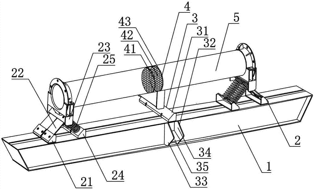
[0038] like figure 1As shown, the overhead gas heat preservation and antifreeze pipeline includes an installation tank 1, a support structure 2, a water collection structure 3, a separation structure 4, and a delivery pipeline 5. There are support structures 2 on both sides of the upper surface of the installation tank 1, and the support structure 2 is erected Conveying pipeline 5, the middle inner wall of conveying pipeline 5 is provided with separation structure 4, and water collection structure 3 communicates with separation structure 4 and conveying pipeline 5 respectively, and separation structure 4 comprises front support frame 41, hollow fiber membrane 42, rear support frame 43, The fiber membrane 42 is radially provided with a drainage channel (not shown in the figure), and the lower wall of the drainage channel is hollowed out.

[0039] It should be noted that the drainage channel is not drawn separately in the figure, because the purpose of this technical solution is...

Embodiment 2

[0046] Such as figure 1 As shown, the overhead gas heat preservation and antifreeze pipeline includes an installation tank 1, a support structure 2, a water collection structure 3, a separation structure 4, and a delivery pipeline 5. There are support structures 2 on both sides of the upper surface of the installation tank 1, and the support structure 2 is erected Conveying pipeline 5, the middle inner wall of conveying pipeline 5 is provided with separation structure 4, and water collection structure 3 communicates with separation structure 4 and conveying pipeline 5 respectively, and separation structure 4 comprises front support frame 41, hollow fiber membrane 42, rear support frame 43, The fiber membrane 42 is radially provided with a drainage channel (not shown in the figure), and the lower wall of the drainage channel is hollowed out.

[0047] It should be noted that the drainage channel is not drawn separately in the figure, because the purpose of this technical solutio...


PUM


Abstract

The invention discloses an overhead gas heat preservation and antifreeze pipeline, which relates to electric heat tracing technology, and is used to solve the problem that the existing eddy current thawing technology is suitable for thawing after dew condensation and freezing in pipelines, and the antifreezing effect is not good for pipelines before dew condensation and freezing. Keeping the cable heated will inevitably cause a problem of energy waste. It includes an installation tank, a support structure, a water collection structure, a separation structure, and a delivery pipeline. Support structures are respectively provided on both sides of the upper surface of the installation tank, and a delivery pipeline is erected on the support structure. structure, the water collecting structure communicates with the separation structure and the conveying pipeline respectively, and the separation structure includes a front support frame, a hollow fiber membrane, and a rear support frame. The purpose of separating water vapor from gaseous C2, C3 and C4 is realized by using the difference in permeability and diffusion speed of gas components in the fiber membrane, and the dew point of the gas is lowered. The invention also provides a method for using the overhead gas heat preservation and antifreeze pipeline.

Description

technical field [0001] The invention relates to electric heat tracing technology, specifically, an overhead gas heat preservation and antifreeze pipeline and a method for using the same. Background technique [0002] The main sources of gas are liquefied petroleum gas, coal gas and mixed air, and gas pipelines are used for gas transmission. Pipelines that transport natural gas (including associated gas produced in oil fields) from mining sites or processing plants to urban gas distribution centers or industrial enterprise users are also called gas transmission pipelines. [0003] Patent document 201510695214.X (application date: 2015.10.23) discloses a self-circulating gas anti-freezing household device, which aims to solve the problem of freezing and blocking of gas pipelines caused by low temperature in winter gas pipelines in cold regions . The device includes: a gas inlet pipe, an outer insulation layer of the gas pipe, and a gas pipe inlet valve, wherein the gas inlet...

Claims


Application Information

Patent Timeline
Patent Type & Authority Applications(China)
IPC IPC(8): F16L53/00F16L55/00F16L3/02
CPCF16L53/00F16L3/02F16L55/00
Inventor 刘有萍杨焱
Owner HEZHOU SITONG INFORMATION TECH CO LTD
Why Eureka
Try Eureka