image forming device

An image and image carrier technology, which is applied to corona discharge devices, electrical recording processes using charge patterns, and equipment using electrical recording processes using charge patterns, etc. , to prevent damage, the effect of large specific surface area

Active Publication Date: 2020-10-09
KYOCERA DOCUMENT SOLUTIONS INC
View PDF5 Cites 0 Cited by
  • Summary
  • Abstract
  • Description
  • Claims
  • Application Information

AI Technical Summary

Problems solved by technology

[0003] However, due to repeated implementation of charge removal by photoelectric charge removal method, part of the photocarrier generated inside the photosensitive layer may remain or accumulate.

Method used


Image

  • image forming device
  • image forming device
  • image forming device

Examples


Embodiment 1

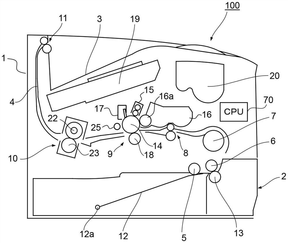
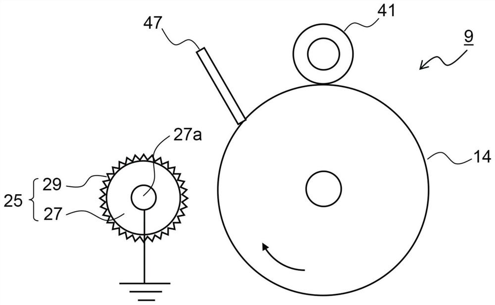
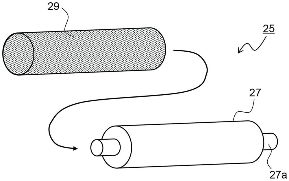
[0092] Use with figure 2 , Figure 5 ~ Figure 7 and Figure 10 In the image forming apparatuses 100 (present inventions 1 to 9) of the first to third embodiments and the fifth embodiment of the image forming unit 9 shown, the decharge performance and durability performance of the decharge roller 25 were evaluated. Regarding the decharge performance, it was checked whether or not a desired post-decharge potential could be obtained after the residual charge of the photosensitive drum 14 was removed by the decharge roller 25 . For durability performance, the presence or absence of streaked images after outputting 50 thousand (50,000) sheets of halftone images with a printing ratio of 25% was confirmed.

[0093] The experimental conditions are as follows: FS-13200 modified machine (manufactured by Kyocera Document Information Systems Co., Ltd.) was used as the image forming apparatus 100, a member in which OPC was laminated on an aluminum tube blank with a diameter of 30 mm was...

Embodiment 2

[0105] use Figure 11 and Figure 12 In the image forming apparatus 100 of the sixth embodiment (the present inventions 10 to 14) in which the magnet member 33 having two magnetic poles with different magnetic forces that become extremely large peaks is arranged inside the photosensitive drum 14, the decharge roller was evaluated. 25 for charge removal performance, image retention and durability. In addition, the image forming apparatus 100 (Comparative Example 5) in which no magnet member is arranged inside the photosensitive drum 14 and the image forming apparatus 100 (Comparative Example 6) in which a magnet member 33 having only one magnetic pole is arranged inside the photosensitive drum 14 are used. to 8), the same evaluation was performed. The test methods, test conditions and evaluation criteria of the charge removal performance and durability performance are the same as in Example 1. With regard to image sticking, the presence or absence of image sticking caused by...

Embodiment 3

[0114] use for Figure 14The eighth embodiment in which the first magnet member 33 a and the second magnet member 33 b are arranged inside the photosensitive drum 14 and the arrangement of the first magnet member 33 a and the second magnet member 33 b is switched according to the state of the image forming apparatus 100 is shown. In the image forming apparatus 100 (present inventions 15 to 20), the decharge performance and durability performance of the decharge roller 25 were evaluated during durable (50,000 sheets) printing and after long-term (8 hours) standing. In addition, the decharge performance and density unevenness of the decharge roller 25 in the half-speed (1 / 2 speed during normal printing) mode, and the decharge performance of the decharge roller 25 during the drum regeneration operation (DR) were also evaluated. and pinhole generation.

[0115] The charge removal performance, the test method, test conditions and evaluation criteria of the durability performance a...


PUM


Abstract

The present invention provides an image forming apparatus. A charge removing device is included for removing electric charges from the member to be discharged by generating a discharge between the member and the member to be discharged, and the discharge member includes a discharge member having a conductive knitted fabric and a support member. The conductive knitted fabric is woven into a tubular shape using a twisted yarn obtained by twisting a plurality of metal fibers. The support member has a cylindrical shape and is inserted into the conductive knitted fabric. In a state where the conductive knitted fabric is grounded or a voltage is applied to the conductive knitted fabric, the discharge member is arranged in a non-contact manner with respect to the member to be discharged. A magnet member is arranged inside the image carrier and inside the charge-removing slit width, which is the width of two tangents to the outer peripheral surface of the discharge member parallel to a straight line passing through the rotation of the image carrier. The center and the axial center of the discharge member, the magnet member has two magnetic poles with different magnetic forces, and the two magnetic poles are arranged inside the width of the charge removal gap.

Description

technical field [0001] The present invention relates to an image forming apparatus including a charge removing device having a discharge member that discharges electricity to a photoreceptor, transfer paper, fixing member, etc. for utilizing electron Image forming devices such as photocopiers, printers, facsimile machines, and their digital composite machines. Background technique [0002] In an image forming apparatus using electrophotography, due to the charge remaining after the toner image on the photosensitive drum (image carrier) is transferred, potential unevenness may occur when the next image is formed. Residual image. Therefore, the photosensitive drum is charged again before the charging process is performed and after the residual charge on the photosensitive drum is removed by the charge removing device. Thereby, the surface of the photosensitive drum can be uniformly charged, and generation of afterimages can be prevented. As a method for removing residual ch...

Claims


Application Information

Patent Timeline
Patent Type & Authority Patents(China)
IPC IPC(8): G03G15/02
CPCG03G15/0291G03G21/06G03G15/2014G03G15/0216D02G3/12
Inventor 清水保猪谷広佳玉置贤一
Owner KYOCERA DOCUMENT SOLUTIONS INC
Why Eureka
Try Eureka