
Quantum image matching method

A matching method, quantum image technology, applied in image analysis, image data processing, instruments, etc., to achieve the effect of improving efficiency

Active Publication Date: 2017-09-26
SHANGHAI MARITIME UNIVERSITY
View PDF2 Cites 11 Cited by
  • Summary
  • Abstract
  • Description
  • Claims
  • Application Information

AI Technical Summary

Problems solved by technology

The scheme proposed in this paper has the following limitations and disadvantages: FRQI representation is used to store quantum images; two quantum images are required to be matched in the same size; a large number of quantum states need to be prepared and multiple measurements are required to obtain two quantum images information about the match
The scheme proposed in this paper has the following limitations and disadvantages: NEQR representation is used to store quantum images, that is, only 2 n ×2 n Quantum images in the form of quantum images; two matching quantum images are required to be of the same size; it is necessary to prepare a large number of quantum states and perform multiple measurements in order to obtain information on the matching degree of two quantum images
The scheme proposed in this paper has the following limitations and disadvantages: use NEQR representation to store quantum images; match smaller quantum template images in larger quantum reference images, but only for one pixel in quantum reference images The pixel value of the point is the same as the pixel value of the pixel point in the upper left corner of the quantum template image; the coordinates of the upper left corner of the matching area can be accurately found by one measurement

Method used


Image

  • Quantum image matching method
  • Quantum image matching method
  • Quantum image matching method

Examples


Embodiment Construction

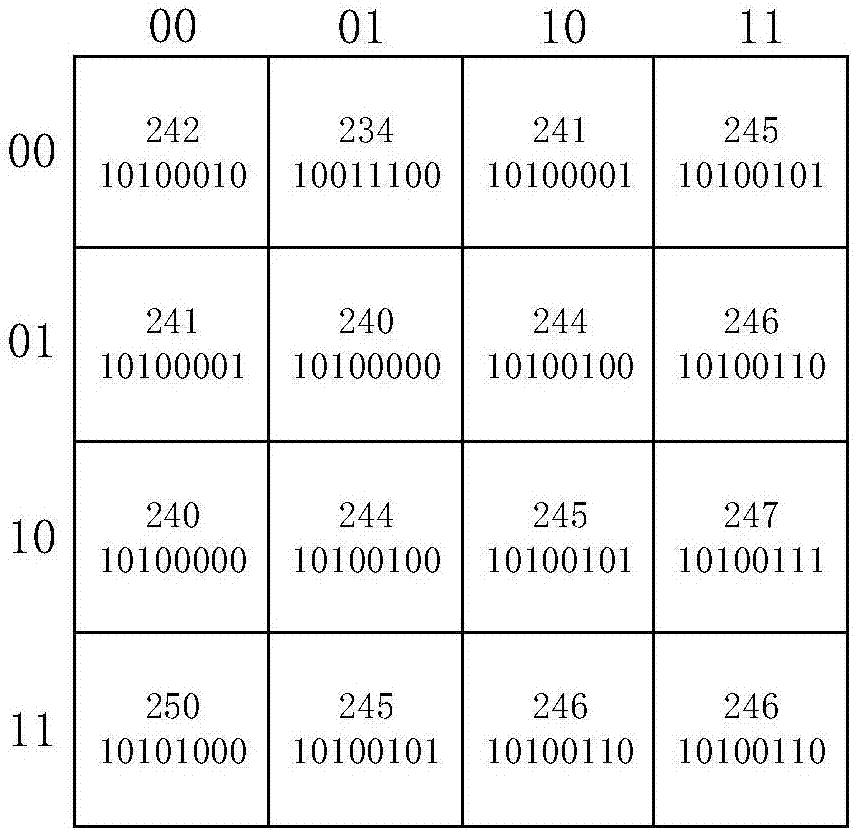
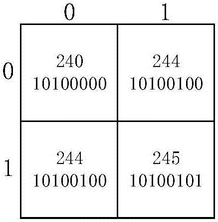
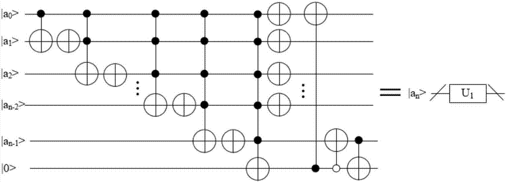
[0048] The following combination Figure 1 to Figure 8 , a preferred embodiment of the present invention is described in detail.

[0049] The invention provides a quantum image matching method, which combines quantum computing with classical computer image matching technology to realize quantum image matching, including the following steps:

[0050] S0, set the size of the quantum reference image to be 2 n ×2 n , the size of the quantum template image is 2 m ×2 m ;

[0051] S1. Use NEQR (Novel Enhanced Quantum Representation, enhanced quantum image representation) to prepare and store the quantum reference image, and obtain the NEQR expression of the quantum reference image|I> 0 ;

[0052] S2. Design the quantum route U of the quantum reference image 0 , corresponding to the input state |I> 0 , the output state of the quantum reference image is obtained as

[0053] S3. No longer use NEQR to prepare and store quantum template images, but use classical image processin...


PUM


Abstract

The invention relates to a quantum image matching method. In combination with quantum calculation and classic computer image matching techniques, the method comprises steps as follows: S0, the size of a quantum reference image is set to be 2<n>*2<n>, and the size of a quantum template image is set to be 2<m>*2<m>; S1, the quantum reference image is prepared and stored in an NEQR manner, and an NEQR expression shown in the specification of the quantum reference image is obtained; S2, a quantum route U0 of the quantum reference image is designed, and the output state, shown in the specification, of the quantum reference image is obtained; S3, the quantum template image is prepared and stored in a classic image processing manner, a quantum route of the quantum template image is designed according to independent basic state expressions adopted for pixel point coordinates and corresponding pixel values, and the output state, shown in the specification, of the quantum template image is obtained; S4, quantum image matching is conducted according to the output state, shown in the specification, of the quantum reference image, the output state, shown in the specification, of the quantum template image as well as two added auxiliary quantum bits. Quantum image matching is realized by use of basic quantum bit gates and modular quantum routes, the matching efficiency is high, and the application range is wide.

Description

technical field [0001] The invention relates to a quantum image matching method, specifically a method for designing and implementing a quantum image matching circuit, and belongs to the technical field of quantum image processing. Background technique [0002] In 1982, Nobel Prize winner Richard Feynman proposed that quantum computers could perform calculations far faster than classical computers. In the 1990s, the quantum prime number factorization algorithm proposed by Shor and the quantum search algorithm proposed by Grover further proved the computing power of quantum computers. [0003] Quantum computers have different structural models, such as quantum Turing machine model, quantum circuit model, cellular automata model, etc. Among them, the quantum circuit model is easier to understand than the other models, but the functions are equivalent. Therefore, the quantum circuit model is usually used to define the quantum computer. Quantum circuits for quantum information...

Claims


Application Information

Patent Timeline
IPC IPC(8): G06T7/32
CPCG06T7/32
Inventor 周日贵刘兴奥
Owner SHANGHAI MARITIME UNIVERSITY
Learn More