
Bridgeless boost type CUK PFC circuit

A step-up type, circuit technology, applied in the direction of electrical components, high-efficiency power electronic conversion, sustainable manufacturing/processing, etc., can solve the problems of the rectifier bridge on-state loss, the improvement of the efficiency of the whole machine, etc., to reduce the conduction The effect of loss and small number

Inactive Publication Date: 2017-09-26
FUZHOU UNIV
View PDF5 Cites 11 Cited by
  • Summary
  • Abstract
  • Description
  • Claims
  • Application Information

AI Technical Summary

Problems solved by technology

[0006] The traditional active power factor correction circuit uses the rectifier bridge as the front-stage AC-DC conversion circuit. At any time, the current must pass through at least three switching devices to form a loop. The on-state loss of the rectifier bridge affects the efficiency of the whole machine.

Method used


Image

  • Bridgeless boost type CUK PFC circuit
  • Bridgeless boost type CUK PFC circuit
  • Bridgeless boost type CUK PFC circuit

Examples


Embodiment Construction

[0025] The technical solution of the present invention will be specifically described below in conjunction with the accompanying drawings.

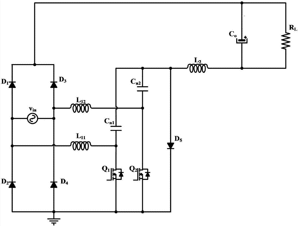
[0026] The present invention provides a bridgeless step-up Cuk PFC circuit, which provides AC-DC power conversion with low ripple, high efficiency and high power factor, such as figure 1 As shown, an input AC voltage source is provided, and an output terminal of the input AC voltage source is respectively connected to a first power diode D 1 anode of a second power diode D 2 The cathode and a first inductor L 11 One end of the input AC voltage source is connected to one end of the input AC voltage source respectively with a third power diode D 3 The anode of a fourth power diode and the cathode of a second inductor L 12 Connected to one end; the first inductance L 11 The other end of each is connected to a first power switch tube Q 1 The drain and a first intermediate capacitor C n1 connected to one end; the second inductance L 12 ...


PUM


Abstract

The invention relates to a bridgeless boost type CUK PFC circuit. The circuit comprises an input AC (alternating current) power supply Vin, a power switch tube Q1, a power switch tube Q2, power diodes (Q1-Q5), intermediate capacitors Cn1 and Cn2, an output capacitor Co and inductors L11, L12 and L2, wherein one end of the input power supply is connected with the anode of D1, the cathode of D2 and one end of L11, and the other end is connected with the anode of D3, the cathode of D4 and one end of L12; the other end of L12 is connected with one end of Cn2 and the drain electrode of Q2; the other end of L11 is connected with one end of Cn1 and the drain electrode of Q1; the other ends of Cn1 and Cn2 are connected to one end of L2 through the anode of D5; the other end of L2 is connected with the negative pole of CO and one end of a load RL; the cathode of D1 is connected with the cathode of D3 and connected with the negative pole of CO and the other end of the load RL; the other ends of D2, D4, Q1 and Q2 and the cathode of D5 are grounded. With the construction of the bridgeless boost type CUK PFC circuit, the conduction loss of power semi-conductor devices is reduced, and low-ripple, efficient and high-power-factor AC-DC (direct current) electrical energy conversion is realized.

Description

technical field [0001] The invention relates to a bridgeless step-up Cuk PFC AC-DC conversion circuit. Background technique [0002] Cuk chopper circuit is also called Cuk converter. The Buck-Boost improved single-tube non-isolated DC converter proposed by Slobodan Cuk of the California Institute of Technology has inductors in the input and output sections, which can significantly reduce the ripple of the input and output currents, and the polarity of the output voltage is opposite to that of the input voltage. , the output voltage can be either lower or higher than the input voltage. [0003] On the basis of the traditional Cuk converter, Slobodan Cuk proposed a step-up Cuk converter in 2000. This kind of converter is only used to realize the boost function of the converter, while retaining the advantages of the traditional Cuk converter, it realizes the unidirectional boost function; at the same time, this kind of converter has the characteristic that the polarity of the...

Claims


Application Information

Patent Timeline
IPC IPC(8): H02M7/06H02M3/07H02M1/14H02M1/42
CPCH02M1/14H02M1/4225H02M1/4241H02M3/07H02M7/06Y02B70/10Y02P80/10
Inventor 林维明林鋆
Owner FUZHOU UNIV
Features
  • Generate Ideas
  • Intellectual Property
  • Life Sciences
  • Materials
  • Tech Scout
  • Unparalleled Data Quality
  • Higher Quality Content
  • 60% Fewer Hallucinations
Learn More