Optical signal device

A technology of optical signals and signal methods, which can be used in railway signals, visual signals, lighting devices, etc., and can solve problems such as compromises and deficiencies

Active Publication Date: 2020-05-15
SIEMENS MOBILITY GMBH
View PDF6 Cites 0 Cited by
  • Summary
  • Abstract
  • Description
  • Claims
  • Application Information

AI Technical Summary

Problems solved by technology

However, due to the combination of light scattering and the reduction of the phantom effect, there is necessarily a compromise, which leads to the fact that the phantom protection is insufficient at least for assemblies of light signaling devices that emit upwards in the close range near the ground

Method used


Image

  • Optical signal device
  • Optical signal device
  • Optical signal device

Examples


Embodiment Construction

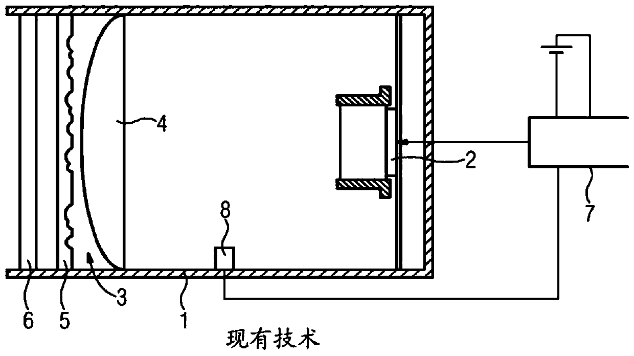
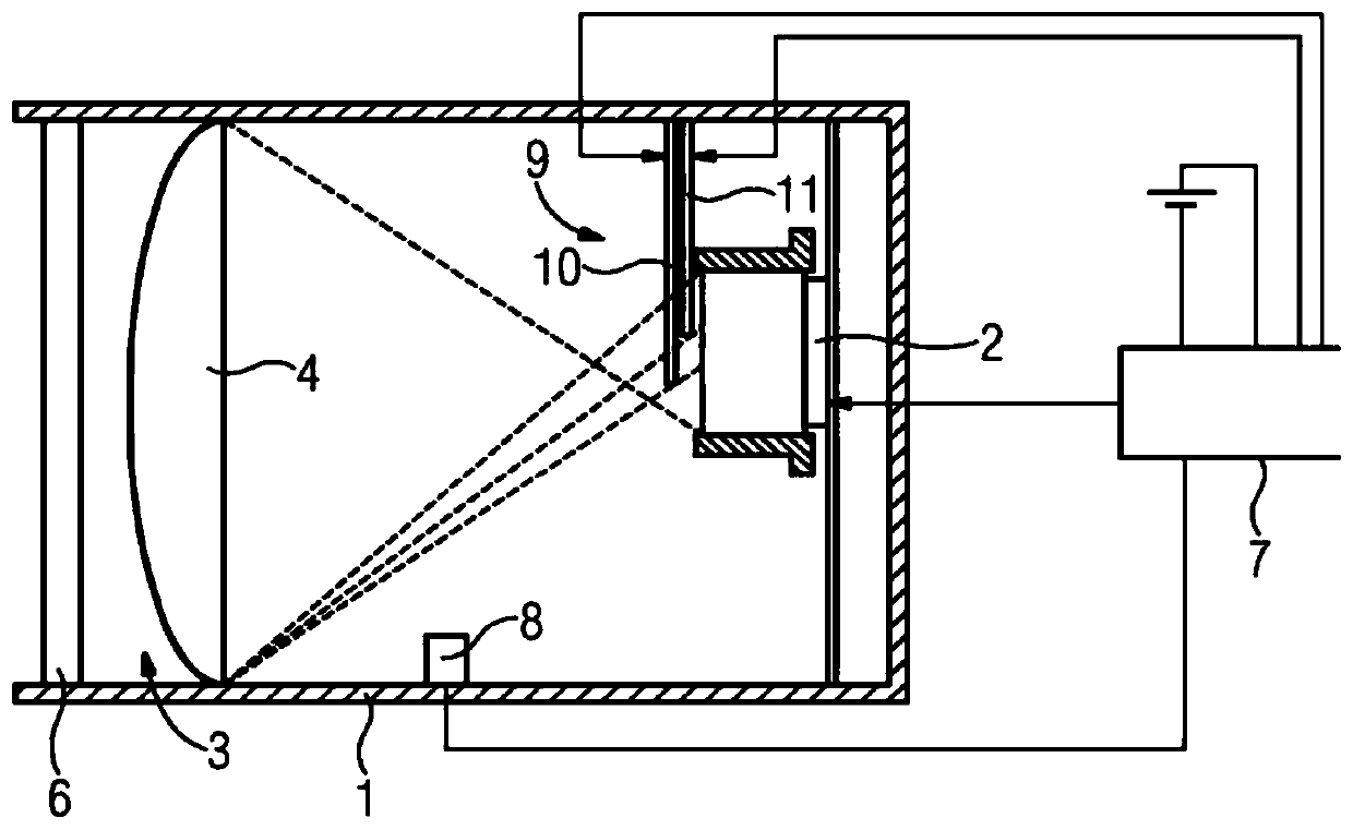
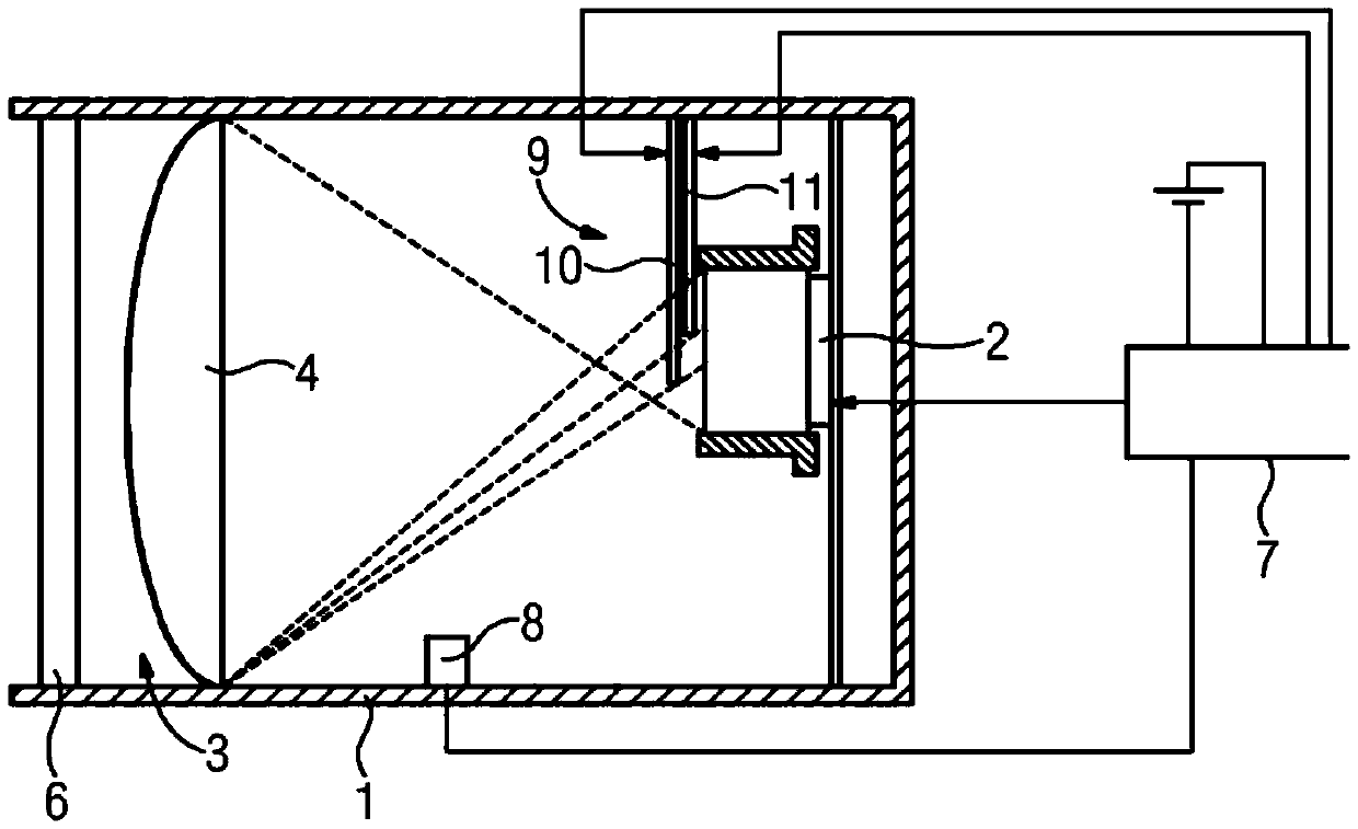
[0020] figure 2 A light signaling device is shown in which a smart glass element 9 is arranged between the LED light source 2 and the optical system 3 . In the present embodiment, the smart glass element 9 consists of two separate smart glass panes 10 and 11 , which protrude into the light flow not as far or to a different extent. In addition to the control signals for the LED light sources 2 , the controller 7 additionally generates control signals for the transmittance of the smart glass panes 10 and 11 . The control signals for the transmittance of the smart glass sheets 10 and 11 can be quite different in order to set the desired light distribution. In this case, ghost effects can be reduced and at the same time close-range and long-range lighting can be carried out while taking into account curves, especially at long distances. Therefore, the usual diffuser 5 / figure 1 . Via the transmission-controllable smart glass element 9 , a significantly more precise adjustabi...


PUM


Abstract

The invention relates to a light signaling device, in particular for rail transit routes, having a controller (7) for controlling a light source (2) and an optical system (3) for visualizing the signal pattern. In order to be able to adjust the brightness limit, the spatial distribution of light and the phantom light intensity more accurately, the present invention provides that an intelligent glass element (9) with controllable transmission is arranged in the aperture section of the light flow.

Description

technical field [0001] The invention relates to a light signaling device, in particular for a rail transit route, having a controller for controlling a light source and an optical system for visualizing the signal pattern. Background technique [0002] In principle, the light signaling device is used as a signaling device or symbol indicator, which transmits specific information by coloring and / or shaping of the luminous surface, ie by reflective properties. This is generally safety-relevant information which must not be visually distorted or obscured by extraneous light under any circumstances. The undesired flare or distortion of points of light due to the incidence of ambient light (such as sunlight or spotlight rays) is known as the phantom effect. In extreme cases, the phantom effect can lead to false displays due to untimely flares or color shifts of the light spots. This effect occurs particularly disturbingly when LED arrangements are used as light sources, since t...

Claims


Application Information

Patent Timeline
IPC IPC(8): B61L5/18F21V9/08
CPCB61L5/1845B61L2207/02F21V9/08G02F1/0105H05B47/105Y02B20/40F21V3/00F21Y2115/10
Inventor R.埃克尔K.凯斯特Z.马林西克
Owner SIEMENS MOBILITY GMBH
Why Eureka
Try Eureka