Method and device for controlling power semiconductor switches connected in parallel

A technology of power semiconductors and control equipment, which is applied in the direction of output power conversion devices, electronic switches, and conversion of AC power input to DC power output. It can solve problems such as aging and failure, and achieve the effect of uniform aging

Active Publication Date: 2017-09-26
ROBERT BOSCH GMBH
View PDF14 Cites 2 Cited by
  • Summary
  • Abstract
  • Description
  • Claims
  • Application Information

AI Technical Summary

Problems solved by technology

Individual power semiconductor switches are more thermally loaded than others, age faster and thus fail faster

Method used


Image

  • Method and device for controlling power semiconductor switches connected in parallel
  • Method and device for controlling power semiconductor switches connected in parallel
  • Method and device for controlling power semiconductor switches connected in parallel

Examples


Embodiment Construction

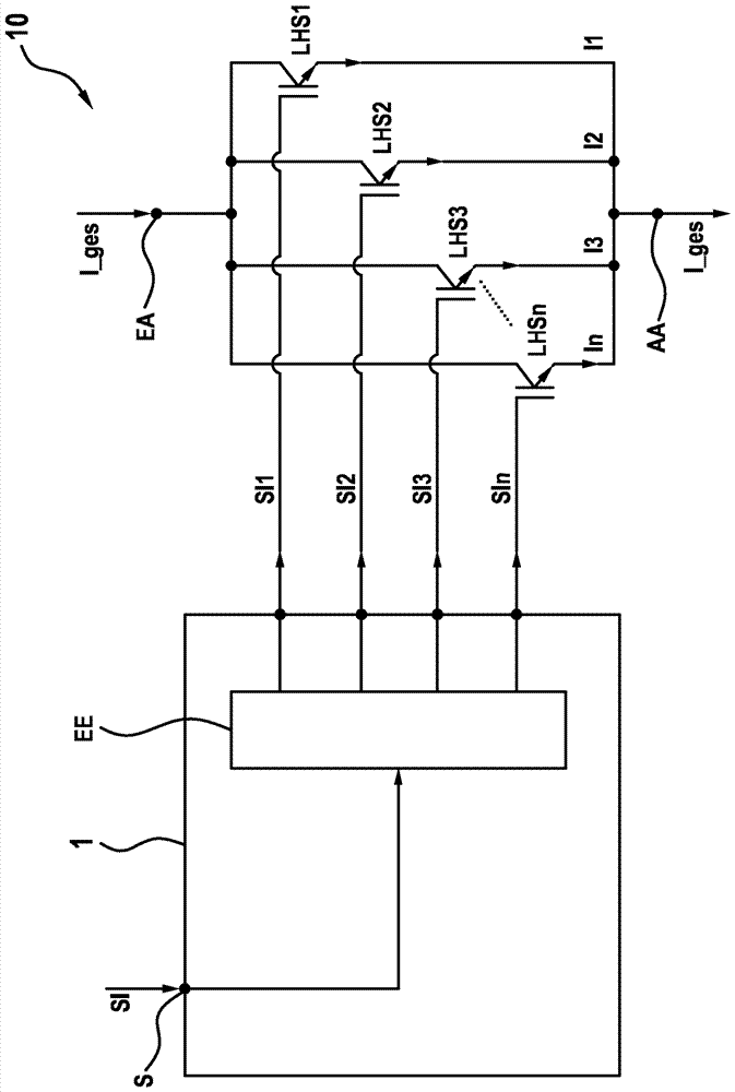
[0047] figure 1 The electrical system 10 is shown schematically. A total current I_ges is supplied to the electrical system 10 at the input terminal EA. The parallel-connected power semiconductor switches LHS1 . . . LHSn are connected on the input side to the input terminal EA and on the output side to the output terminal AA. The total current I_ges is distributed to the power semiconductor switches that are closed, ie have a closed state. Accordingly, the sum of the individual currents I1 . . . In via the respective parallel-connected power semiconductor switches LHS1 . . . LHSn always corresponds to the total current I_ges. The total current I_ges is discharged via the output terminal AA. The parallel-connected power semiconductor switches LHS1 . . . LHSn are used both for current conduction and for interrupting the current flow from the input terminal EA to the output terminal AA. The parallel-connected power semiconductor switches LHS1 . . . LHSn each have a gate conne...


PUM


Abstract

The invention relates to a method (200) and a control device (1) for controlling at least two power semiconductor switches (LHS1..LHSn) connected in parallel for switching a total current (I_ges). The at least two power semiconductor switches (LHS1..LHSn) connected in parallel each have a gate terminal for controlling the respective power semiconductor switch (LHS1..LHSn). An input terminal (EA) for feeding the total current (I_ges), an output terminal (AA) for discharging the total current (I_ges), and a joint control terminal (S) for receiving a joint control signal (SI) that has the state 'disconnect' or 'connect' are provided. The at least two power semiconductor switches (LHS1..LHSn) connected in parallel are connected to the input terminal (EA) at the input end and to the output terminal (AA) at the output end. At least one ascertainment unit (EE) is designed to receive the joint control signal (SI) at the input end, ascertain at least two individual control signals (SI1..SIn) in accordance with the joint control signal (SI) in order to control the at least two power semiconductor switches (LHS1..LHSn), and output the at least two ascertained individual control signals to the gate terminals of the at least two power semiconductor switches at the output end. The at least two individual control signals (SI1..SIn) each have the state 'disconnect' or 'connect' and differ at least temporarily.

Description

technical field [0001] The invention relates to a method and a control device for controlling parallel-connected power semiconductor switches. The invention also relates to an electrical system with the control device, a computer program for carrying out the method, and an electronic storage medium. Background technique [0002] An inverter is usually used for operating an electric drive, which converts the electrical energy in a DC voltage source, such as a battery, into an AC voltage in order to supply an electric machine, such as an asynchronous machine, with AC voltage or AC current. For this purpose, the inverter has a so-called half bridge. The half bridge has power semiconductor switches, by means of which a direct current and a direct voltage are switched sequentially, so that an alternating voltage and an alternating current are formed at the output terminals of the inverter. For these power semiconductor switches, an upper current limit is predetermined, which is...

Claims


Application Information

Patent Timeline
Patent Type & Authority Applications(China)
IPC IPC(8): H03K17/12H02M1/088H02M1/32
CPCH02M1/088H02M1/32H03K17/127H02M7/53806H02M7/5387
Inventor S.布茨曼P.陶费尔B.埃克特
Owner ROBERT BOSCH GMBH
Why Eureka
Try Eureka