Utilization of antenna beam information

A technology of antenna beams and beams, which is applied in the field of computer programs and computer program products, can solve the problems of reduced cell coverage capacity and performance degradation, etc.

Active Publication Date: 2017-09-26
TELEFON AB LM ERICSSON (PUBL)
View PDF6 Cites 1 Cited by
  • Summary
  • Abstract
  • Description
  • Claims
  • Application Information

AI Technical Summary

Problems solved by technology

The first method introduces additional signaling overhead
The second approach is prone to poor selection of antenna parameters and/or poor identificati

Method used


Image

  • Utilization of antenna beam information
  • Utilization of antenna beam information
  • Utilization of antenna beam information

Examples


Embodiment Construction

[0031] The inventive concepts will now be described more fully hereinafter with reference to the accompanying drawings, in which specific embodiments of the invention are shown. However, inventive concepts may be embodied in many different forms and should not be construed as limited to the embodiments set forth herein. Rather, these embodiments are given by way of example so that this disclosure will be thorough and complete, and will fully convey the scope of the inventive concept to those skilled in the art. Throughout the specification, like symbols refer to like elements. Any steps or features shown by dashed lines should be considered optional.

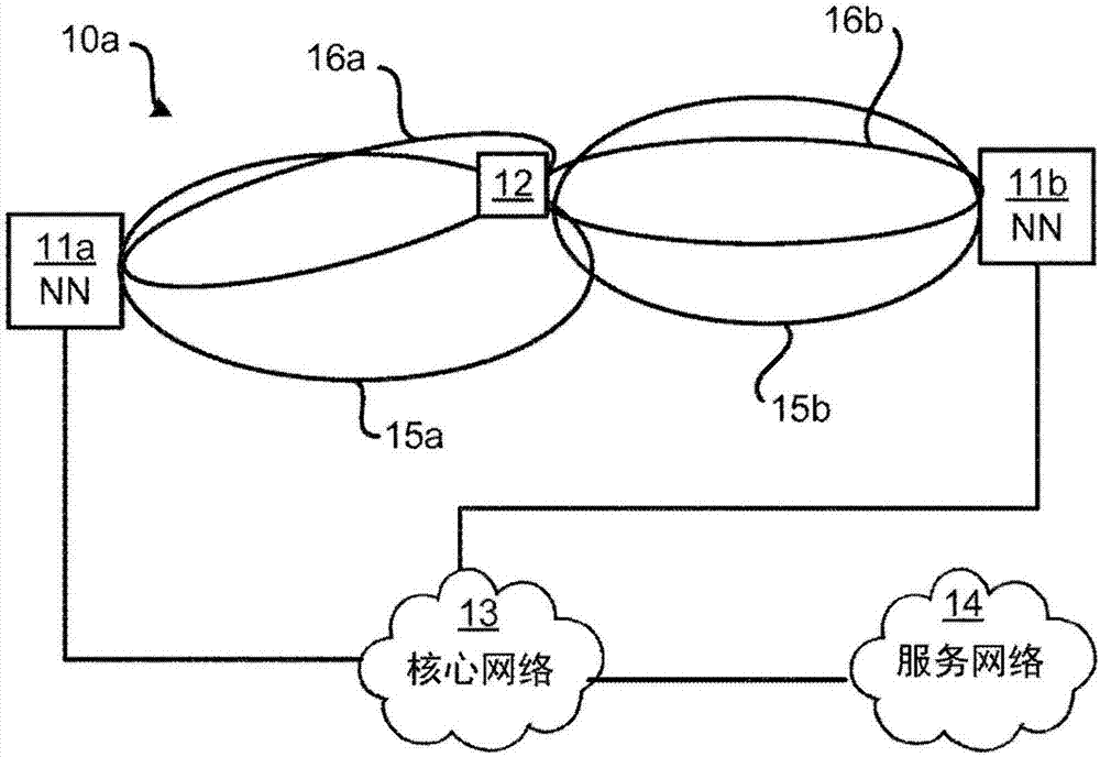
[0032] Figure 1a is a schematic diagram illustrating a communication network 10a to which embodiments presented herein may be applied. The communication network 10a comprises network nodes 11a, 11b. Each network node 11 a , 11 b provides network coverage for wireless devices, one of which is indicated with reference numeral ...


PUM


Abstract

There is provided a method for utilizing antenna beam information. The method is performed by a network node. The method comprises acquiring antenna beam information indicative of a direction of a wireless device (WD) specific beam of the network node. The method comprises classifying the acquired antenna beam information into a cell specific beam category based on an angular difference between the direction and a direction of main lobe of a cell specific beam of the network node. The method comprises performing at least one of a load balancing action of the wireless device and a radiation beam pattern change related to the cell specific beam category.

Description

technical field [0001] Embodiments presented herein relate to antenna beam information, in particular to methods, network nodes, computer programs and computer program products utilizing antenna beam information. Background technique [0002] In a communication network, it can be a challenge to obtain good performance and capacity for a given communication protocol, its parameters, and the physical environment in which the communication network is deployed. [0003] Currently, advanced antenna settings and techniques enable ever-increasing throughput and robustness in wireless communication networks. One such technique is to shape the beams of the antenna array (ie, perform beamforming). Currently, beamforming can be achieved using so-called reconfigurable antenna systems (RAS). [0004] A cell-specific beam refers to an antenna beam pattern generated to provide cell-specific reference symbol (CRS) coverage for a cell in a communication network. The beam pattern is simila...

Claims


Application Information

Patent Timeline
IPC IPC(8): H04B7/06H04W16/28H04W28/08
CPCH04B7/0617H04B7/063H04W16/28H04W28/0861H01Q3/26H04B7/06H04B7/0621
Inventor 普拉迪帕·拉玛钱德拉哈拉德·卡琳帕纳吉塔·里奥鲁克里斯蒂娜·赛特贝克
Owner TELEFON AB LM ERICSSON (PUBL)
Why Eureka
Try Eureka