Maze crossed type conduction oil drying cylinder with two-side oil supply

A heat transfer oil, labyrinth technology, used in textiles and papermaking, papermaking machines, dryers, etc., can solve problems such as differences in the degree of drying of paper, achieve uniform flow, improve transfer efficiency, and improve the effect of drying function

Pending Publication Date: 2017-09-29
QILU UNIV OF TECH +1
View PDF6 Cites 3 Cited by
  • Summary
  • Abstract
  • Description
  • Claims
  • Application Information

AI Technical Summary

Problems solved by technology

However, the average temperature difference on both sides of the inlet and outlet is still greater than 5°C. When drying the pulp, it is still necessary to artificially adjust the hot oil, and the degree of dryness of the obtained paper is still different.

Method used


Image

  • Maze crossed type conduction oil drying cylinder with two-side oil supply
  • Maze crossed type conduction oil drying cylinder with two-side oil supply
  • Maze crossed type conduction oil drying cylinder with two-side oil supply

Examples


Embodiment Construction

[0015] Further description will be made below in conjunction with the accompanying drawings and specific embodiments.

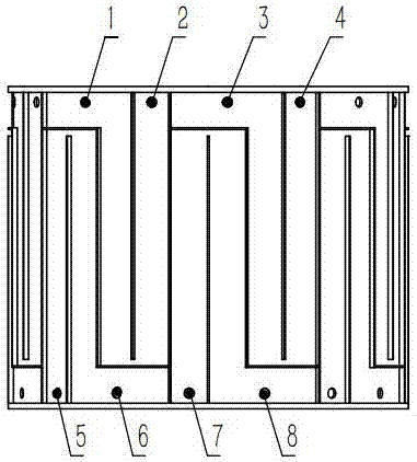
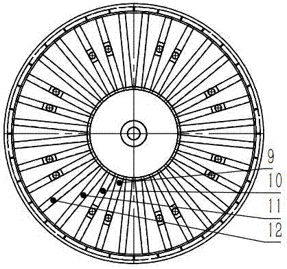
[0016] The present invention as figure 1 , 2 , 3, and 4 are a kind of pulp drying heat conduction oil cylinder for papermaking, which has a new type of heat conduction oil cylinder with double-sided inflow and a labyrinth channel for the oil guide chamber. and some metal hoses for description of the implementation.

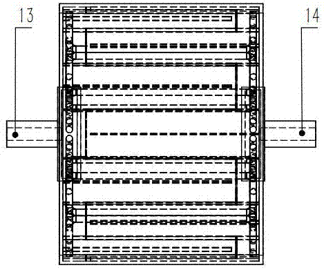
[0017] image 3 As shown, hot oil flows in from the shaft head on the inlet side of 13. With the rotation of the hot oil cylinder and the continuous storage of hot oil in the shaft head, the hot oil gradually accumulates. After reaching a certain level, the hot oil begins to flow out, and the hot oil inside the shaft head is continuously increased. , until the air in the shaft head and the oil guide chamber is completely exhausted.

[0018] figure 2 As shown, the hot oil inside the shaft head flows out of the shaft head on the inlet side an...


PUM


Abstract

Provided is a conduction oil drying cylinder for drying paper pulp. The whole cylinder adopts welded steel, wherein maze type conduction oil cavities are distributed on the cylindrical surface of the conduction oil drying cylinder in a crossed mode, and an oil inlet and an oil outlet connected with the conduction oil cavities are connected with the left side and the right side of each conduction oil cavity; the inner structure of each conduction oil cavity comprises 32 conduction oil cavity channels and 32 metal hoses, and each two channels are communicated through a welded baffle; a baffle is welded at the tail ends of the first conduction oil cavity and the second conduction oil cavity, a baffle is welded at the beginning ends of the third conduction oil cavity and the fourth conduction oil cavity, the rule of the baffles is executed after the 32nd conduction oil cavity is executed; conduction oil flows in from the right end of the conduction oil cavities, turns, and enters the second channel to flow reversely when about to reach the bottom of the cylinder; when flowing to the end of the second conduction oil cavity, the conduction oil turns again by 90 degrees to flow out from the end of the third conduction oil cavity, and part of the conduction oil flows to the beginning end of the fourth conduction oil cavity. Through the above structure, hot oil passes through two adjacent conduction oil cavities so as to complete heat exchange fully and transfer more energy, and the temperature difference of the surfaces of the cylinder filled with the hot oil is smaller, and can be reduced to within 0.5 DEG C.

Description

technical field [0001] The invention relates to a heat-conducting oil dryer, in particular to a heat-conducting oil dryer for paper pulp drying. Background technique [0002] Patent No. CN202323525U describes a steel welded heat conduction oil dryer, which is a one-side straight oil inlet type, and the surface temperature distribution of the oil cylinder is better than that of a conventional hot oil cylinder, which can obtain better paper quality, save materials and reduce heat loss. The utilization rate of heat can reach 90%. However, the average temperature difference on both sides of the inlet and outlet is still greater than 5°C. When drying the pulp, it is still necessary to artificially adjust the hot oil, and the degree of dryness of the obtained paper is still different. Contents of the invention [0003] The purpose of the present invention is to obtain a pulp drying heat conduction oil cylinder for papermaking with a more uniform surface temperature distribution...

Claims


Application Information

Patent Timeline
Patent Type & Authority Applications(China)
IPC IPC(8): D21F5/02
CPCD21F5/021D21F5/022
Inventor 王丽冯益华张文泉张记云李东利高永法
Owner QILU UNIV OF TECH
Why Eureka
Try Eureka