Optical sub module and optical module

An optical sub-module and optical component technology, applied in the field of optical communication, can solve the problem of weak adhesion between the side wall of the cover plate and the side wall of the casing.

Active Publication Date: 2017-09-29
HISENSE BROADBAND MULTIMEDIA TECH
View PDF4 Cites 10 Cited by
  • Summary
  • Abstract
  • Description
  • Claims
  • Application Information

AI Technical Summary

Problems solved by technology

[0005] This application provides an optical sub-module and an optical module to solve the technical problem that the high-temperature curing of the adhesive leads to the weak bonding between the side wall of the cover plate and the side wall of the housing

Method used


Image

  • Optical sub module and optical module
  • Optical sub module and optical module
  • Optical sub module and optical module

Examples


Embodiment Construction

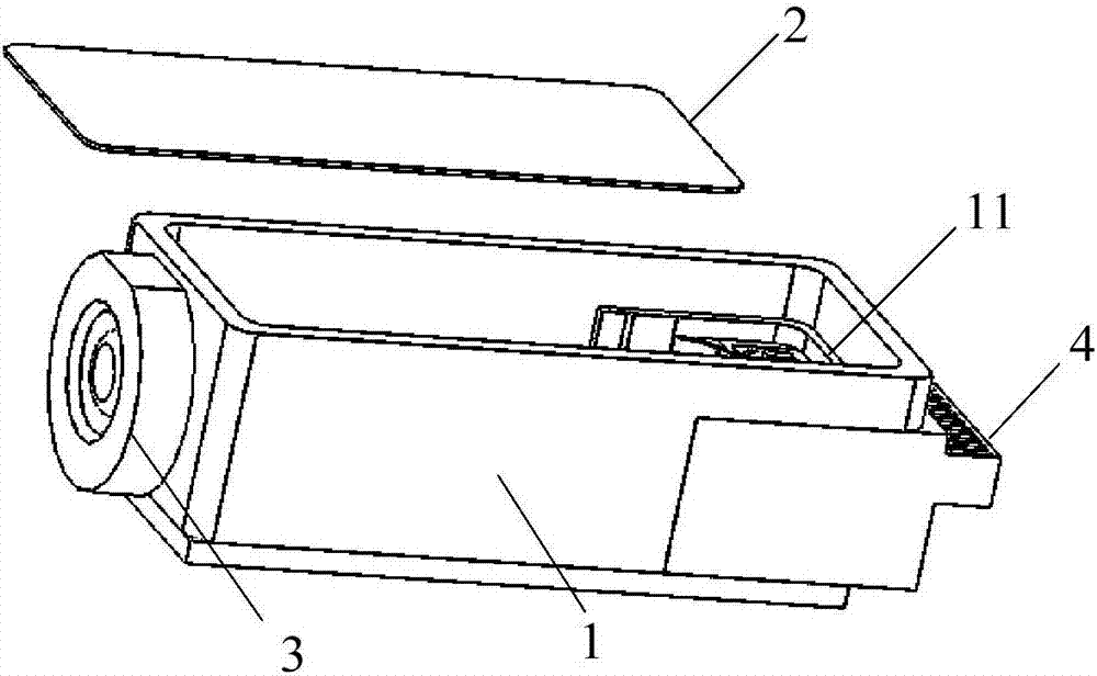
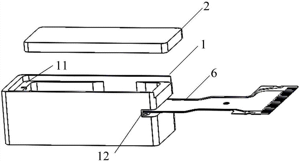
[0022] In view of the technical problem that the air inside the cavity is easy to be heated and expanded during the curing of the adhesive, so that the cover plate 2 is easily lifted by the internal hot air, which affects the sealing performance of the optical module, this application proposes an optical sub-module, which The core idea is: through the height difference between one of the side walls of the housing 1 and the other three side walls, a U-shaped structure with one side opening is formed on the upper end surface of the housing 1 . When encapsulating the optical sub-module, glue can be applied on the support plates 11 of the above-mentioned three side walls, and after the cover plate 2 is covered on the upper surface of the housing 1, the adhesive is cured. The hot air generated during the curing of the adhesive will be discharged from the gap between the other side wall and the cover plate 2 . Therefore, the force of the hot air inside the housing 1 will not adverse...


PUM


Abstract

The invention discloses an optical sub module and an optical module. The optical sub module comprises a shell, a cover plate, an optical assembly, a flexible board and an optical window, wherein the shell comprises a bottom surface and four side walls vertical to the bottom surface, the inner surfaces of the side walls are provided with supporting plates with the same height, the height of one side wall is the same as that of the supporting plate, the heights of the other three side walls are larger than that of the supporting plate, and the cover plate is in sealed connection with the supporting plates; the flexible plate provides electric connection for the optical assembly; and optical connection between the optical assembly and the outer part through the optical window is realized. When the optical sub module is packaged, rubber coating is carried out on supporting plates on the higher side walls, after the cover plate covers the supporting plates, an adhesive is cured, hot air generated during the curing process of the adhesive is discharged from a gap between the lower side plate and the cover plate, and thus, the acting force of the hot air inside the shell does not generate bad influences on fixing of the cover plate, and the sealing performance of the optical sub module is ensured.

Description

technical field [0001] The present application relates to the technical field of optical communication, in particular to an optical sub-module and an optical module. Background technique [0002] The optical module is an important device to realize photoelectric conversion or electro-optical conversion in the optical fiber communication system, and can include an optical receiving sub-module, an optical transmitting sub-module or an integrated optical transceiver module. The optical component is one of the core components of the optical sub-module. figure 1 It is a schematic diagram of the optical path of a typical 40G / 100G TOSA (Optical Transmitter Submodule). Depend on figure 1 It can be seen that the optical components in the light emitting sub-module include 4 lasers, 4 collimating lenses respectively corresponding to the lasers, an optical multiplexing component for combining 4 paths of light into 1 path of light, and 1 focusing lens from the light emitting end. The ...

Claims


Application Information

Patent Timeline
Patent Type & Authority Applications(China)
IPC IPC(8): G02B6/42
CPCG02B6/4256G02B6/4268G02B6/4281
Inventor 杜光超唐永正李丹刘维伟
Owner HISENSE BROADBAND MULTIMEDIA TECH
Why Eureka
Try Eureka