
Permanent magnet synchronous motor control method and system

A technology of permanent magnet synchronous motor and control method, which is applied in the direction of control system, vector control system, motor generator control, etc., and can solve problems such as motor starting failure and large switching current

Active Publication Date: 2017-09-29
GUANGDONG MEIZHI COMPRESSOR
View PDF3 Cites 6 Cited by
  • Summary
  • Abstract
  • Description
  • Claims
  • Application Information

AI Technical Summary

Problems solved by technology

[0005] The purpose of the embodiments of the present invention is to provide a control method and system for a permanent magnet synchronous motor, which is used to solve the large problem caused by the direct switching of the permanent magnet synchronous motor from the open-loop starting circuit to the closed-loop working circuit in the prior art. Technical issues with switching current and failure of the motor to start

Method used


Image

  • Permanent magnet synchronous motor control method and system
  • Permanent magnet synchronous motor control method and system
  • Permanent magnet synchronous motor control method and system

Examples


Embodiment Construction

[0033] The specific implementation manners of the embodiments of the present invention will be described in detail below with reference to the accompanying drawings. It should be understood that the specific implementations described here are only used to illustrate and explain the embodiments of the present invention, and are not used to limit the embodiments of the present invention.

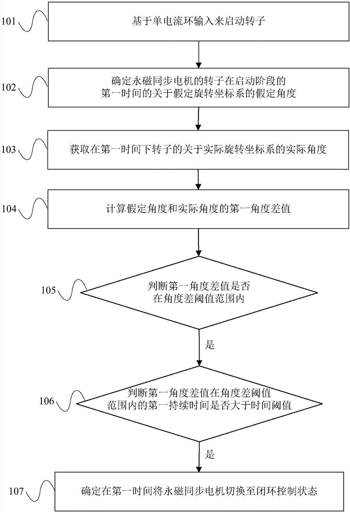
[0034] See figure 1 Shown is a schematic flow chart of a method for controlling a permanent magnet synchronous motor according to an embodiment of the present invention. The method specifically includes:

[0035] Step 101: Start the rotor based on the single current loop input;

[0036] Step 102: Determine the assumed angle of the rotor of the permanent magnet synchronous motor with respect to the assumed rotating coordinate system at the first time during the startup phase;

[0037] Step 103: Obtain the actual angle of the rotor with respect to the actual rotating coordinate system at the first time;...


PUM


Abstract

The embodiments of the invention provide a permanent magnet synchronous motor control method and a system, which belong to the field of permanent magnet synchronous motor control. The permanent magnet synchronous motor control method comprises the following steps: determining the assumed angle of the rotor of a permanent magnet synchronous motor relative to an assumed rotation coordinate system at a first time in the start stage; acquiring the actual angle of the rotor relative to an actual rotation coordinate system at the first time; calculating a first angle difference between the assumed angle and the actual angle, and judging whether the first angle difference is within an angle difference threshold range; if the first angle difference is within the angle difference threshold range, judging whether a first duration in which the first angle difference is within the angle difference threshold range is greater than a time threshold; and if the first duration is greater than the time threshold, switching the permanent magnet synchronous motor to a closed-loop control state. Thus, the stability and robustness of motor closed-loop switching-in can be improved.

Description

Technical field [0001] The invention relates to the field of permanent magnet synchronous motor control, in particular to a permanent magnet synchronous motor control method and system. Background technique [0002] With the rapid development of motor technology, the motors of some air conditioner cooling fans and compressors are permanent magnet synchronous motors without position sensors. Before starting the position sensorless permanent magnet synchronous motors, the position of the rotor is unknown. The parameters estimate the rotor position and start the motor after the rotor position is estimated. [0003] In related technologies, it is common to use the back-EMF model to drive the compressor of the air conditioner or refrigerator and use this to estimate the position angle and speed of the rotor. This implementation method has been widely promoted due to its simple operation, and more specifically about Single current start mode: After the compressor frequency is increased ...

Claims


Application Information

Patent Timeline
Patent Type & Authority Applications(China)
IPC IPC(8): H02P6/21H02P6/08H02P21/18
CPCH02P6/08H02P6/21H02P21/18
Inventor 叶斌英任新杰宋万杰
Owner GUANGDONG MEIZHI COMPRESSOR
Learn More