Noise reduction structure of engine oil bottom shell

An engine oil and noise reduction technology, which is applied in the direction of engine lubrication, oil pan, engine components, etc., can solve the problems of high cost of transformation, poor technical effect, high cost, etc., and achieve fast transformation, good noise reduction effect, The effect of low renovation cost

Inactive Publication Date: 2017-10-03
ANHUI TECHN COLLEGE OF MECHANICAL & ELECTRICAL ENG
View PDF0 Cites 0 Cited by
  • Summary
  • Abstract
  • Description
  • Claims
  • Application Information

AI Technical Summary

Problems solved by technology

[0006] 1. The noise reduction effect is not good. Although there are many noise reduction solutions for the oil pan in the existing technology, the technical effect is not good. This may be due to the defects in the design ideas of these existing technologies, or it may be that The design of the specific structure is not fine enough;
[0007] 2. The cost of renovation is high, and the current solutions for noise reduction include reinforcing the inside of the oil pan and coating expensive damping materials outside the oil pan, etc.
Among them, the reinforcement scheme needs to redesign the casting mold, and the cost of producing thin-walled complex components is also very high, so the cost of modifying the oil pan has remained high for a long time
Although the vibration of the oil pan contributes a lot to the noise, it is well known that the oil pan itself does not play a vital role in the performance of the engine, that is, the modification of the oil pan is not very important. Greatly improved engine performance
However, the current car users are very concerned about the cost performance and power performance of the car. Therefore, it is inevitable that car manufacturers should not invest too much in the transformation of the oil pan. Therefore, the problem of high transformation cost still needs to be solved.

Method used


Image

  • Noise reduction structure of engine oil bottom shell
  • Noise reduction structure of engine oil bottom shell
  • Noise reduction structure of engine oil bottom shell

Examples


Embodiment 1

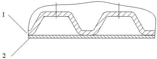
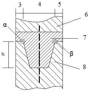
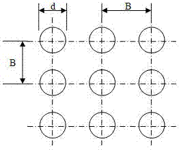
[0032] The noise reduction structure includes: engine oil pan; resonant sound-absorbing plate, the resonant sound-absorbing plate is set on the inner side wall of the engine oil pan, and there are several through holes on the resonant sound-absorbing plate, the holes on the resonant sound-absorbing plate are circular The diameter of the circular hole is d, the center distance of the circular hole is B, the perforation rate σ is proportional to the square of the ratio of d and B, and σ is 0.01, and the diameter d is 3mm; and high damping vibration isolation Rubber pad, the high damping vibration isolation rubber pad is set between the top end surface of the oil pan and the connection surface of the crankcase, the high damping vibration isolation rubber pad includes the first part, the second part and the third part, the high damping vibration isolation rubber pad The cross-sections of the first and second parts are rectangular, the cross-section of the third part of the high-dam...

Embodiment 2

[0034] Replace some parameters in Example 1 as follows: σ is 0.08, diameter d is 6.5mm; height (h) of the trapezoidal part is 30mm, first inclination angle (α) is 80° and second inclination angle (β) is 77 °, the length of the bottom side of the third part is greater than the sum of the lengths of the bottom sides of the first part and the second part. Among them, the thickness of the resonant sound-absorbing panel is 6 mm, and the thickness of the resonant sound-absorbing panel is smaller than the diameter d, and the B range of the resonant sound-absorbing panel is 16 mm. The first angle of inclination is 3° greater than the second angle of inclination, the length of the bottom side of the first portion is the same as the length of the bottom side of the second portion, and the length of the bottom side of the third portion is three times the length of the bottom side of the first portion The high-damping vibration-isolation rubber pad has a three-layer structure, in which bu...

Embodiment 3

[0036] Replace some of the parameters in Example 1 as follows: σ is 0.04, diameter d is 5mm; the height (h) of the trapezoidal part is 20mm, the first inclination angle (α) is 70° and the second inclination angle (β) is 68 °, the length of the bottom side of the third part is greater than the sum of the lengths of the bottom sides of the first part and the second part. Wherein, the thickness of the resonant sound-absorbing panel is 4 mm, and the thickness of the resonant sound-absorbing panel is smaller than the diameter d, and the B range of the resonant sound-absorbing panel is 15 mm. The first angle of inclination is 2° greater than the second angle of inclination, the length of the bottom side of the first portion is the same as the length of the bottom side of the second portion, and the length of the bottom side of the third portion is three times the length of the bottom side of the first portion times, the high-damping vibration-isolation rubber pad is a single-layer s...


PUM


Abstract

The invention provides a noise reduction structure of an engine oil bottom shell. The noise reduction structure comprises an engine oil bottom shell, a resonance sound absorption board, and further comprises a high damping and vibration isolation rubber pad, wherein the resonance sound absorption board is arranged inside the side wall of the engine oil bottom shell; a plurality of through holes are formed in the resonance sound absorption board, and the holes in the resonance sound absorption board are circular; the high damping and vibration isolation rubber pad is arranged between the top end surface of the oil bottom shell and the connecting surface of a crankshaft box; the high damping and vibration isolation rubber pad comprises a first part, a second part and a third part; the section of the first part of the high damping and vibration isolation rubber pad and the section of the second part of the high damping and vibration isolation rubber pad are rectangular; and the section of the third part of the high damping and vibration isolation rubber pad is trapezoidal. Compared with the prior art, the noise reduction structure is good in noise reduction effect and is low in manufacturing cost.

Description

technical field [0001] The invention relates to a noise reduction structure, in particular to a noise reduction structure of an engine oil pan. Background technique [0002] The internal combustion engine is composed of various parts and systems such as piston, connecting rod crank mechanism, gas distribution mechanism, body, intake and exhaust systems, and cooling fan. In the engine work engineering, the cylinder mainly completes a series of complex processes such as air intake, fuel injection in the cylinder, fuel combustion, and gas discharge after combustion, and finally converts the heat energy generated by fuel combustion into mechanical work. The generation of process-related component noise is also very complicated, and the overall engine noise is composed of component noise from various sound sources closely related to the above-mentioned process. [0003] Mechanical noise is another very important noise source in the engine. Generally, the mechanical noise in the ...

Claims


Application Information

Patent Timeline
Patent Type & Authority Applications(China)
IPC IPC(8): F01M11/00
CPCF01M11/0004F01M2011/0008
Inventor 倪晋挺国树东赵起超王岩周润
Owner ANHUI TECHN COLLEGE OF MECHANICAL & ELECTRICAL ENG
Why Eureka
Try Eureka