Self-adaption compressor for improving flow of rotor blade tip and stator angular region

An adaptive, compressor technology, applied in the direction of machines/engines, liquid fuel engines, components of pumping devices for elastic fluids, etc., can solve problems such as unfavorable performance, performance degradation, mainstream flow field interference, etc., to achieve The effect of widening the range of effective working angle of attack, increasing the circulation volume and diffusion capacity, and improving the working ability

Active Publication Date: 2017-10-03
BEIHANG UNIV
View PDF5 Cites 16 Cited by
  • Summary
  • Abstract
  • Description
  • Claims
  • Application Information

AI Technical Summary

Problems solved by technology

[0002] In the flow inside the aero-engine, the flow inside the compressor is subjected to a strong reverse pressure gradient due to the small space, which makes the flow field have a complex vortex structure; the corner separation structure located at the stator end area and the rotor blade tip The leakage flow structure of the compressor is the main secondary flow structure inside the compressor, and it is the main source of flow loss and blockage inside the compressor. Cause compressor stall and surge, bring catastrophic consequences; after decades of research, many researchers have had a deep understanding of compressor stator corner flow and rotor tip flow, but due to its Due to the limitation of space and the complexity of the flow, the effective control of the flow in the compressor has not been well realized according to the existing research results; Self-circulation adjustment mechanism, while using and improving the flow structure that is not conducive to performance, to a

Method used


Image

  • Self-adaption compressor for improving flow of rotor blade tip and stator angular region
  • Self-adaption compressor for improving flow of rotor blade tip and stator angular region
  • Self-adaption compressor for improving flow of rotor blade tip and stator angular region

Examples


Embodiment Construction

[0030] The specific implementation manner of the present invention will be further described in detail below in conjunction with the accompanying drawings and examples.

[0031] (1) Limit cycle mode:

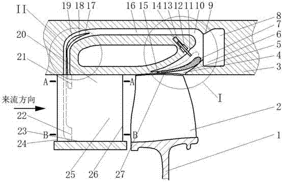
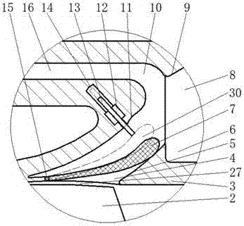
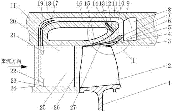
[0032] Such as figure 1 , figure 2 As shown, a kind of self-adaptive compressor of the present invention that improves rotor blade tip and stator angle area flow comprises the stator vane 20 that is positioned at upstream, the rotor blade 2 that is positioned at downstream and casing 3 that has bleed air circulation chamber 10; There is a blade tip gap 27 between the blade tip and the casing; the bleed air circulation chamber 10 is located inside the casing 3 and is composed of the bleed air circulation chamber inlet 4 , the high-pressure gas stabilizing chamber 8 and the main bleed air pipe 16 .

[0033]The inlet 4 of the bleed air circulation cavity is located above the rotor blade tip clearance 27, and its 4 inlet section is composed of a flexible inlet side wall 7 in the ...


PUM


Abstract

The invention relates to the technical field of aircraft gas turbines and discloses a self-adaption compressor for improving flow of a rotor blade tip and a stator angular region. The self-adaption compressor comprises a stator blade, a rotor blade and a casing with a gas introducing circulation cavity. The gas introducing circulation cavity is formed inside the casing and composed of a gas introducing circulation cavity inlet, a high-pressure gas pressure-stabilizing cavity and a main gas introducing pipe. A flexible inlet side wall hinged to the inlet can regulate and control the open degree under the pressure differential effect in a self-adaption mode. The ultimate open degree position of the inlet is restrained by a hydraulically-controlled limiting supporting rod and a check block in the ultimate position of the flexible inlet side wall. The different ultimate open degrees can be set under different work states and are regulated within the open-degree range in a self-adaption mode. Through a self-circulation gas introducing structure, leakage flow of the rotor blade tip of the compressor and separation flow of the stator angular region of the compressor are improved. Through a foreign matter separating device, foreign matter entering the compressor is removed timely, and stable operation of the compressor is guaranteed. Through the high-pressure gas pressure-stabilizing cavity, needed high-pressure gas is provided for an aircraft and an engine.

Description

technical field [0001] The invention relates to the technical field of aviation gas turbines, in particular to an adaptive gas compressor for improving the flow in the rotor blade tip and stator corner area. Background technique [0002] In the flow inside the aero-engine, the flow inside the compressor is subjected to a strong reverse pressure gradient due to the small space, which makes the flow field have a complex vortex structure; the corner separation structure located at the stator end area and the rotor blade tip The leakage flow structure of the compressor is the main secondary flow structure inside the compressor, and it is the main source of flow loss and blockage inside the compressor. Cause compressor stall and surge, bring catastrophic consequences; after decades of research, many researchers have had a deep understanding of compressor stator corner flow and rotor tip flow, but due to its Due to the limitation of space and the complexity of the flow, the effec...

Claims


Application Information

Patent Timeline
IPC IPC(8): F04D29/66
CPCF04D29/667F04D27/023F04D27/0238
Inventor 唐雨萌柳阳威陆利蓬王鸣
Owner BEIHANG UNIV
Why Eureka
Try Eureka