Vehicle travelling dynamic measurement system and measurement method thereof

A dynamic measurement and vehicle driving technology, applied in the direction of measuring devices, weighing, instruments, etc., can solve the problems that the outer contour and weight of the vehicle cannot be measured at the same time, the length, width and height cannot be measured at the same time, and the speed of the vehicle is limited, so as to overcome cheating Driving phenomena, improving the efficiency of overrun detection, and improving the effect of accuracy

Pending Publication Date: 2017-10-03
山西省信息产业技术研究院有限公司
View PDF7 Cites 10 Cited by
  • Summary
  • Abstract
  • Description
  • Claims
  • Application Information

AI Technical Summary

Problems solved by technology

However, the existing laser measurement of vehicle length, width and height and traditional weighing solutions still have major defects: firstly, the length, width and height of vehicles in the same lane cannot be measured at the same time, and the length, width and height need to be measured after measuring the width and height, which takes a long time to detect; The second is to measure the length, width and height of the vehicle. Multiple laser scanning sensors need to be installed, which is complex and costly. The third is that the outer contour and weight of the vehicle cannot be measured at the same time. , which reduces the detection efficiency; at the same time, using the traditional weighing device, the vehicle is prone to cheating, resulting in inaccurate measurement data

Method used


Image

  • Vehicle travelling dynamic measurement system and measurement method thereof
  • Vehicle travelling dynamic measurement system and measurement method thereof
  • Vehicle travelling dynamic measurement system and measurement method thereof

Examples


Embodiment Construction

[0040] The present invention will be further described below in conjunction with the accompanying drawings, but this description is only used to explain the present invention, not to limit the present invention.

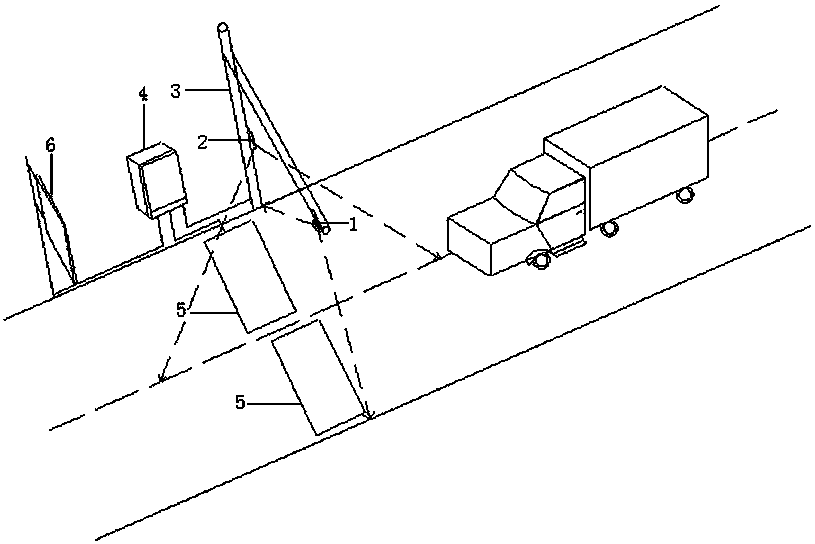
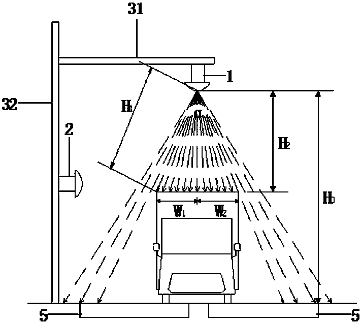
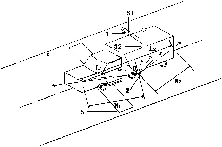
[0041] The vehicle driving dynamics measurement system of the present invention includes a first laser scanning sensor 1, a second laser scanning sensor 2, an L-shaped pole 3, a main controller 4, a split dislocation weighing scale 5, an LED display 6; an L-shaped pole 3 It includes a crossbeam 31 and a vertical pole 32, the crossbeam is located at the top of the vertical pole and is perpendicular to the vertical pole, the distance between the crossbeam and the ground is set at 6m-7m; the first laser scanning sensor 1 is installed on the L-shaped vertical pole crossbeam 31, the second The installation position of a laser scanning sensor 1 is directly above the center line of each lane, and the second laser scanning sensor 2 is installed on the L-shaped vertical pole 3...


PUM


Abstract

The invention relates to a vehicle travelling dynamic measurement system and a measurement method thereof. The measurement system and the measurement method have the advantages of high measurement precision and stable performance. The measurement system includes a first laser scanning sensor, a second laser scanning sensor, an L-shaped upright pole, a main controller, a split dislocation type weighing scale and an LED display; the installation position of the first laser scanning sensor is located just above each lane center line; the scanning plane of the first laser scanning sensor is perpendicular to the ground and the traveling direction of a vehicle; an included angle between the scanning plane of the second laser scanning sensor and a vertical pole ranges from 28 degrees to 32 degrees; the scanning plane of the second laser scanning sensor intersects with the lane center line; the LED display, the L-shaped upright pole and the main controller are located on a straight line; the straight line is parallel to a lane traveling direction; the main controller is connected with the first laser scanning sensor and the second laser scanning sensor through network cables; and the main controller is connected with the split dislocation type weighing scale and the LED display through an RS232/RS485 serial port line. According to the method, the length, width and weight of the vehicle are measured separately.

Description

technical field [0001] The invention relates to the field of road transportation overrun detection, in particular to a vehicle running dynamic measurement system and a measurement method thereof. Background technique [0002] In recent years, with the rapid development of road transportation, the number and proportion of large freight vehicles, trucks with trailers and container transport vehicles in the transportation vehicles have been increasing. Affected by the economic structure and profit-driven, some transport vehicles have excessively refitted the size of the compartments of the vehicles in order to one-sidedly pursue profits, resulting in the widespread phenomenon of over-limit transport. Overrun transportation is very harmful, severely damages the infrastructure of roads and bridges, shortens the service life of roads and bridges, and brings great hidden dangers to traffic safety. At present, my country has done a lot of research on vehicle overrun detection. The ...

Claims


Application Information

Patent Timeline
Patent Type & Authority Applications(China)
IPC IPC(8): G01B11/04G01G19/03G01G19/52
CPCG01B11/04G01G19/03G01G19/52
Inventor 王文逾吕俊哲张国华程保喜高晶刘涛王远明杨常华张建清赵向南尉东晓刘卫军
Owner 山西省信息产业技术研究院有限公司
Why Eureka
Try Eureka