Fiber-array-based multi-channel fluorescence detection system

A technology of optical fiber array and fluorescence detection, applied in the field of fluorescence signal detection system, can solve the problem of slow imaging speed of CMOS camera

Inactive Publication Date: 2017-10-03
上海戴泽光电科技有限公司
View PDF7 Cites 4 Cited by
  • Summary
  • Abstract
  • Description
  • Claims
  • Application Information

AI Technical Summary

Problems solved by technology

But for CMOS cameras, it is point-to-surface imaging, that is, the scanning system scans a sample point, and the image plane of this point will be formed in the imaging system, resulting in a relatively slow imaging speed of the CMOS camera.

Method used


Image

  • Fiber-array-based multi-channel fluorescence detection system
  • Fiber-array-based multi-channel fluorescence detection system
  • Fiber-array-based multi-channel fluorescence detection system

Examples


Embodiment Construction

[0027] The present invention will be described in detail below in conjunction with specific embodiments. The following examples will help those skilled in the art to further understand the present invention, but do not limit the present invention in any form. It should be noted that those skilled in the art can make several changes and improvements without departing from the concept of the present invention. These all belong to the protection scope of the present invention.

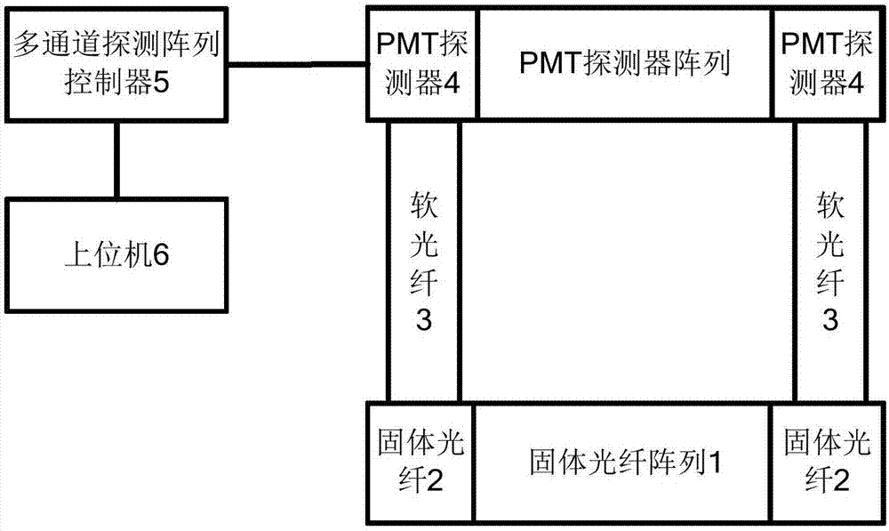
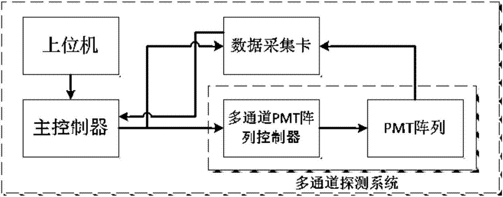
[0028] The invention discloses a multi-channel detection system based on an optical fiber array, wherein the solid optical fiber array receives fluorescent signals and transmits the signals to soft optical fibers, and the soft optical fibers are connected to the PMT detection array and transmit the signals to the multi-channel PMT array. The machine-controlled multi-channel PMT array controller receives optical signals and converts them into analog signals. The data acquisition card converts the analog s...


PUM


Abstract

The invention provides a fiber-array-based multi-channel fluorescence detection system. A solid-state optical fiber array receives a fluorescence signal and transmits the signal to a flexible fiber; and the flexible fiber is connected to a PMT detection array and transmits the signal to the PMT array. An upper computer controls the multi-channel PMT array to receive an optical signal and transform the optical signal into an analog signal; and a data acquisition card converts the analog signal into a digital signal and returns the digital signal to a main controller. The fixed fiber is used for replacing the pinhole in the traditional confocal system and the fiber array forms the pinhole surface of the confocal system, thereby realizing super-resolution imaging of the confocal system.

Description

technical field [0001] The invention relates to the technical field of fluorescence signal detection systems, in particular, to a fluorescence detection system based on an array detector. Background technique [0002] Confocal microscopes often place a pinhole and point detector on the imaging detection surface, which effectively suppresses stray light on the non-focus plane, and the pinhole is located at the imaging focal plane. In order to improve the tomographic imaging capability of the confocal system, The pinholes (that is, pinholes) are often set very small. In theory, the smaller the pinhole size, the higher the imaging resolution. However, if the pinhole size is set too small, the light signal passing through the pinhole will be weakened, and the imaging How to reduce the size of the pinhole while ensuring the brightness of the image is one of the concerns of the confocal system. [0003] Using a CMOS camera with tiny pixels to replace the pinhole and point detecto...

Claims


Application Information

Patent Timeline
Patent Type & Authority Applications(China)
IPC IPC(8): G02B21/00G02B21/36G01J1/42
CPCG02B21/0076G01J1/4228G02B21/365
Inventor 刘春祥胡洁何涛黄海清戚进沈健胡方凯
Owner 上海戴泽光电科技有限公司
Why Eureka
Try Eureka