Eureka AIR delivers breakthrough ideas for toughest innovation challenges, trusted by R&D personnel around the world.

Novel charging gun and manufacturing method thereof

A manufacturing method and charging gun technology, applied in charging stations, electric vehicle charging technology, circuits, etc., can solve problems such as increased production costs and production processes, short circuit of charging guns, poor waterproof performance, etc., to ensure charging effect and safety, Effect of improving overall strength and excellent waterproof performance

Active Publication Date: 2017-10-10
SHENGLAN TECH CO LTD
View PDF6 Cites 3 Cited by
  • Summary
  • Abstract
  • Description
  • Claims
  • Application Information

AI Technical Summary

Problems solved by technology

[0003] First, the charging handle of the current charging gun is generally formed first and then spliced ​​with other parts. Not only the overall strength of the charging gun is low, but also the waterproof performance is poor. Because there are many electrical components in the charging gun, rainwater The existence of the charging gun can easily cause short circuit and damage; due to the large number of parts, a large number of production lines and operators are required for assembly work
[0004] Second, the surface and tail of the existing charging handle have no wrapping layer, which not only makes the hand feel poor, but also causes surface aging when the charging gun is outdoors for a long time. Although some charging guns have a wrapping layer, and the tail has no soft material, the charging wire For long-term use, because there is no buffer at the end of the charging handle, it is easy to break off from the tail of the charging handle; although some charging guns are equipped with a wrapping layer, the tail of the charging handle (commonly known as the end) is formed separately and then set on the cable. The waterproof performance is poor, and the production cost and production process are increased
[0005] Third, there is no fixed ring on the charging wire. When the charging gun is used, the charging wire will be dragged, and the wire will directly act on the charging terminal, which will easily cause a break between the charging terminal and the charging wire. The breakage will increase the resistance and heat during charging. security risks
Although there are fixing rings on some charging wires, since the charging handle does not use in-mold injection molding process, the structure of the fixing ring is complicated and the production cost is high

Method used


Image

  • Novel charging gun and manufacturing method thereof
  • Novel charging gun and manufacturing method thereof
  • Novel charging gun and manufacturing method thereof

Examples


Embodiment Construction

[0051]The following will clearly and completely describe the technical solutions in the embodiments of the present invention with reference to the drawings in the embodiments of the present invention.

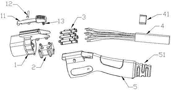
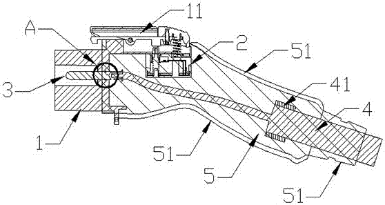
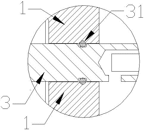
[0052] see figure 1 and figure 2 , in the embodiment of the present invention, a new type of charging gun and its manufacturing method, comprising, a charging plug 1, a charging terminal 3 and a charging wire 4, the upper end of the charging plug 1 is provided with a locking member 11 that is buckled with a socket at one end, The middle part of the locking member 11 is fixedly connected to the charging plug 1 through a fixing pin 12, and a spring 13 is provided between the other end of the locking member 11 and the charging plug 1. When the spring 13 springs up, the locking member 11 The other end of the locking member 11 moves upward under the action of the spring 13, and one end of the locking member 11 moves downward with the fixed pin 12 as the axial direction, so that th...


PUM


Abstract

A novel charging gun comprises a charging plug, a charging terminal and a charging wire, a locking piece is arranged at the upper end of the charging plug, one end of the locking piece is buckled with a socket, and a spring is arranged at the other end of the locking piece and can bounce to prevent the locking piece from disengaging from the socket; the charging plug is also provided with a control switch, and the control switch is fixedly connected with the charging plug through a screw; the charging terminal is clamped in the charging plug, and the charging terminal is fixedly connected with the charging wire; the charging gun also comprises a charging handle, and the charging handle, the charging plug, the charging terminal, the charging wire and the control switch are integrally formed through the injection molding process. According to the novel charging gun, the waterproof problem in outdoor use is solved, the strength problem generated when rolling tests of vehicles are conducted is solved, the assembly process problem generated when assembly is mainly completed in moulds in a station is solved, assembly lines are greatly reduced, the cost is reduced, and a part of components such as a tail part of the charging handle are saved.

Description

technical field [0001] The invention relates to the field of new energy vehicle charging, in particular to a new charging gun manufactured by a new technology and a manufacturing method thereof. Background technique [0002] With the continuous development of our society and the continuous improvement of our domestic economic level, our residents' awareness of environmental protection has gradually increased, and their demand for low-carbon life and low-carbon economy has become increasingly strong. Most of the cars nowadays use the internal combustion engine as the drive core, which will emit a lot of car exhaust when in use. As one of the main sources of air pollution, automobile exhaust contains a large number of harmful substances, which have a far greater impact on the human body than nitrogen oxides and hydrocarbons. Therefore, for the automotive industry, people are urgently seeking new engine technology to replace the traditional internal combustion engine technolog...

Claims


Application Information

Patent Timeline
Patent Type & Authority Applications(China)
IPC IPC(8): B60L11/18H01R13/639H01R13/52H01R43/20
CPCH01R13/5202H01R13/639H01R43/20B60L53/16Y02T10/70Y02T10/7072Y02T90/14
Inventor 曾杰军雷开国胡永涛钟勇光
Owner SHENGLAN TECH CO LTD
Why Eureka
Eureka Blog
Learn More