Backlight display module device based on array-type laser quantum dot sticks

A backlight display and quantum dot technology, which is applied in optics, nonlinear optics, instruments, etc., can solve the problems of wide light source and inability to make good use of the advantages of quantum dots, and achieve the effect of eliminating the light guide plate and simplifying the structure

Pending Publication Date: 2017-10-10
NANJING 55TH INSTION TECH DEV
View PDF20 Cites 0 Cited by
  • Summary
  • Abstract
  • Description
  • Claims
  • Application Information

AI Technical Summary

Problems solved by technology

However, the excitation light source is a blue LED. Since the LED is a broad-spectrum light source, the spectrum of the light source is very wide, and the advantages of quantum dots cannot be well utilized. Therefore, there is an urgent need for an excitation light source with a purer color, so that the formation of quantum dots Broad-spectrum color gamut is wider and the colors are more pure

Method used


Image

  • Backlight display module device based on array-type laser quantum dot sticks
  • Backlight display module device based on array-type laser quantum dot sticks
  • Backlight display module device based on array-type laser quantum dot sticks

Examples


Embodiment Construction

[0026] The present invention will be described in detail below in conjunction with the accompanying drawings.

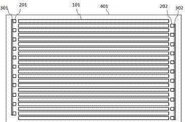
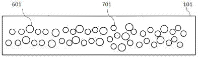
[0027] like figure 1 as shown, figure 1 It is the overall structure of the arrayed laser quantum dot rod backlight module, including at least one excitation point light source 201, quantum dot rod 101 and liquid crystal display device 503, the quantum dot rod 101 forms an array, and the excitation point light source 201 is blue The blue laser light source is coupled with the quantum dot rods 101 through an optical coupling component, and corresponds to each other, and is arranged in a rectangular array on a plane parallel to the display panel.

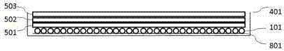
[0028] A backplane 401 is provided, and the array of quantum dot rods 101 is located in the middle part of the backplane 401 laterally. Metal brackets are provided on both sides of the backplane 401, which are respectively a left metal bracket 301 and a right metal bracket 302. The excitation point light source 201 is fixed ...


PUM

PropertyMeasurementUnit
Wavelengthaaaaaaaaaa
Poweraaaaaaaaaa

Abstract

The invention relates to a backlight display module device based on array-type laser quantum dot sticks. The backlight display module device includes at least one stimulating point light source (201), the quantum dot sticks (101) and a liquid crystal display panel (503), and is characterized in that the quantum dot sticks (101) form an array; the stimulating point light sources (201) are blue laser light sources, and the blue laser light sources are coupled with the quantum dot sticks (101) through optical coupling units in a one-to-one correspondence mode, and are distributed on a plane parallel to the display panel in a rectangular array mode. Scattering particles are doped in the quantum dot sticks for increasing brightness, and distributed in the axial direction of the quantum dot sticks in a gradient distribution mode. The backlight display module device based on the array-type laser quantum dot sticks can control wave length of the light sources, brightness and power consumption of laser devices, length of the quantum dot sticks and size of the displayer, so that the backlight display module device is an ideal laser backlight and display device.

Description

technical field [0001] The invention relates to the field of laser display and lighting, in particular to an array type laser quantum dot rod backlight display module device. Background technique [0002] With the development of social science and technology, people have higher and higher requirements for the optical performance of displays. From early fluorescent tube backlit displays to current LED backlit displays. At the same time, from computer display, to mobile phone, to large screen, to home theater, all reflect the development of display technology. However, any technology has its limitations. Although LED has become a hot spot in the market today and has been greatly popularized, there are still development bottlenecks in some aspects, especially in terms of brightness, stability and color gamut. Therefore, people are trying to develop new technologies to improve existing products, and the laser as a light source is at the right time. [0003] As a light source,...

Claims


Application Information

Patent Timeline
IPC IPC(8): G02F1/13357
CPCG02F1/133602G02F1/133614
Inventor 张玉平宋文陈亮焦成
Owner NANJING 55TH INSTION TECH DEV
Why Eureka
Try Eureka