Thin-walled concrete tie screw waterstop structure and process

A concrete, thin-walled technology, applied in building construction, on-site preparation of building components, connection of formwork/template/work frame, etc. problems such as low strength, to achieve the effect of improving the ability to resist the water pressure on the upstream surface, high structural tightness and durability, and improving the impermeability strength

Active Publication Date: 2017-10-13
河南省水利第一工程局集团有限公司
View PDF5 Cites 2 Cited by
  • Summary
  • Abstract
  • Description
  • Claims
  • Application Information

AI Technical Summary

Problems solved by technology

[0003] In thin-walled concrete projects, the current construction market has the following problems in the process of pulling screw-jointed formwork: the quality requirements for the complete processing and manufacturing process of screw-pull and water-stop are high, installation is difficult, and it is not easy to remove the formwork; for thin-walled concrete, the concrete The wall is thin, the pull screw is short, the seepage diameter (seepage diameter refers to the water penetration path) is short, and the screw rod is prone to leakage after long-term corrosion; due to the thin concrete wall and dense steel bars, it is easy to cause over-vibration during pouring and vibrating. Leakage caused by damage to the water-stop steel ring of the pull screw and the expansion ring or leakage of vibration at the water-stop steel ring of the pull screw
The advantage of this type of water-stopping method is that it has high water pressure resistance (in contrast, the increase in water pressure is not easy to cause further leakage, but it cannot solve the original leakage)
The disadvantages are: difficult construction, slow progress, high construction cost, poor durability, easy to leak due to structural reasons, etc.
The disadvantage is that the water pressure resistance is small, and it is easy to cause leakage due to water pressure

Method used


Image

  • Thin-walled concrete tie screw waterstop structure and process
  • Thin-walled concrete tie screw waterstop structure and process
  • Thin-walled concrete tie screw waterstop structure and process

Examples


Embodiment Construction

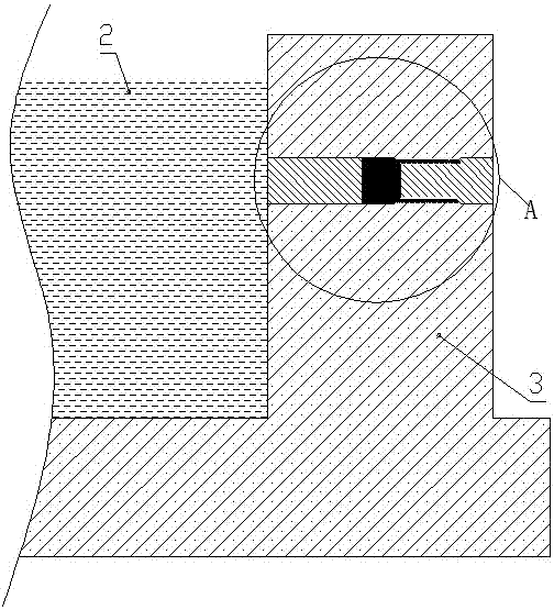
[0038] figure 1 and figure 2 The water at the thin-walled concrete structure 3 is indicated by the middle symbol 2.

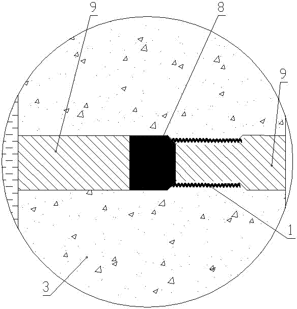
[0039] Such as Figure 1 to Figure 5 As shown, the thin-walled concrete anti-screw water-stop structure of the present invention includes a plastic bellows 1 arranged in the thin-walled concrete anti-screw hole; shape.

[0040] Taking the water-facing surface as the forward direction, the pull screw hole in front of the plastic corrugated pipe 1 is set as the front reaming section 4, the diameter of the front reaming section 4 is larger than the diameter of the plastic corrugated pipe 1 and the rear end of the front reaming section 4 is set There is a front contraction hole segment 5 with a large front and a small rear. The diameter of the rear end of the front contraction hole segment 5 is the same as the outer diameter of the plastic bellows 1 and communicates with the plastic bellows 1 correspondingly; The inner diameters of the screw holes are the same...


PUM


Abstract

The invention discloses a thin-walled concrete tie screw waterstop structure, comprising a plastic bellows arranged in a thin-walled concrete tie screw hole; the part of the tie screw hole in front of the plastic bellows is a front reamed hole, the part of the tie screw hole in rear of the plastic bellows is provided with a rear reamed hole, the tail end of the front reamed hole is provided with a water-swellable waterstop plug, and all the front reamed hole, the rear reamed hole and the plastic bellows are sealed with grout. The invention also discloses a construction method of the thin-walled concrete tie screw waterstop structure; the construction method comprises the steps of first, mounting a plastic bellows sleeve and tie screws; second, pouring, and removing forms; third, reaming; fourth, mounting the water-swellable waterstop plug; fifth, filling with grout; sixth, adding a water-swellable waterstop lug to the backwater side in case of underground water. The thin-walled concrete tie screw waterstop structure has high hydraulic pressure resistance, high structural tightness and durability, and good convenience of construction.

Description

technical field [0001] The invention relates to the field of building construction, in particular to a thin-walled concrete anti-screw water-stop structure and a water-stop technology. Background technique [0002] In the construction of concrete engineering, it is a common technical means to tie the inner and outer formwork of the wall by using the pull bolts (also known as pull screws or pull screws) between the formwork on both sides. The pull screws bear the lateral pressure of the concrete. and other loads to ensure that the rigidity and stability of the inner and outer formwork meet the design requirements. [0003] In thin-walled concrete projects, the current construction market has the following problems in the process of pulling screw-jointed formwork: the quality requirements for the complete processing and manufacturing process of screw-pull and water-stop are high, installation is difficult, and it is not easy to remove the formwork; for thin-walled concrete, th...

Claims


Application Information

Patent Timeline
Patent Type & Authority Applications(China)
IPC IPC(8): E04G17/00E04G17/065
CPCE04G17/007E04G17/0657
Inventor 郭全中马志华畅军孔晨旭畅会军潘景茹刘雪利
Owner 河南省水利第一工程局集团有限公司
Why Eureka
Try Eureka