Disc-type permanent magnetic coupling mechanism and devices using same

A permanent magnet coupling, disc technology, applied in electromechanical devices, permanent magnet clutches/brakes, electric brakes/clutches, etc. High speed regulation accuracy, wide speed regulation range, easy to make effects

Active Publication Date: 2017-10-13
JIANGSU MAGNET VALLEY TECH
View PDF4 Cites 17 Cited by
  • Summary
  • Abstract
  • Description
  • Claims
  • Application Information

AI Technical Summary

Problems solved by technology

Therefore, the eddy current permanent magnetic coupler is only suitable for fans and pump loads
[0009] 2) It cannot adjust the speed in a wide range
In the case of large-scale speed regulation, the slip is very large, which means that the slip power is large, which will cause the copper plate to heat up more seriously
Therefore, the eddy current permanent magnet coupler is not suitable for a wide range of speed regulation operation, and is only suitable for occasions where the moment of inertia is small, the speed regulation range is small, and short-term operation
[0010] 3) A mechanical operating mechanism is required
According to the current processing technology at home and abroad, when the diameter of the iron core is greater than 500mm, it will be difficult to ensure the lamination coefficient of the iron core
Limited by the processing technology of the disc core, the power of the winding disc permanent magnetic coupling speed control device is not large, and the manufacturing cost is relatively high

Method used


Image

  • Disc-type permanent magnetic coupling mechanism and devices using same
  • Disc-type permanent magnetic coupling mechanism and devices using same
  • Disc-type permanent magnetic coupling mechanism and devices using same

Examples


Embodiment 1

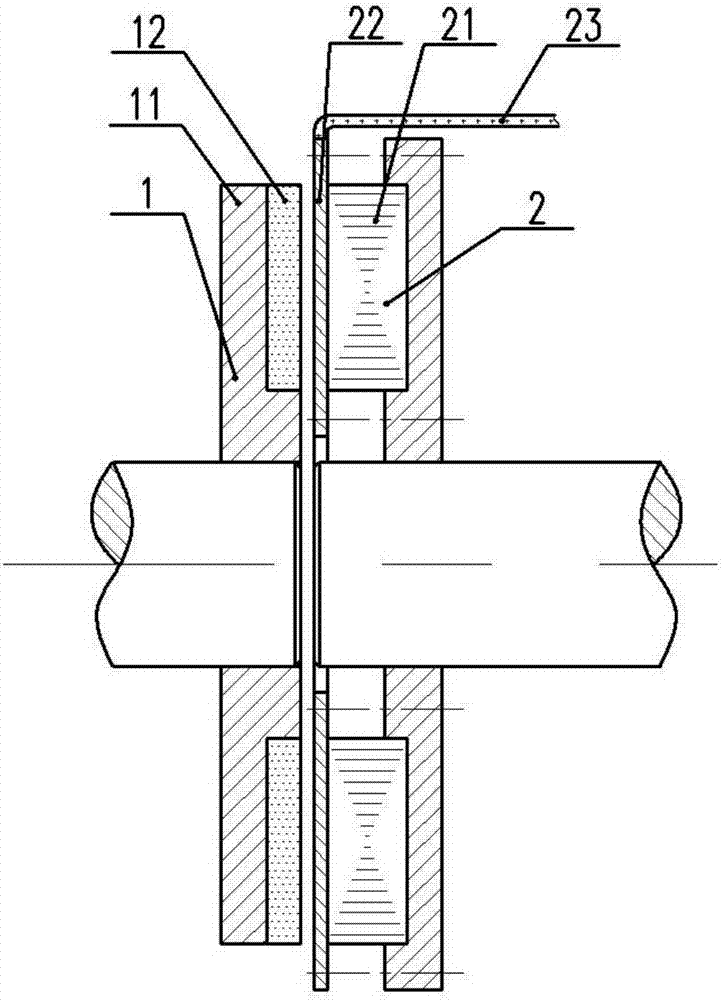
[0095] like Figure 3-5 As shown, a preferred embodiment of the present invention relates to a disk-type permanent magnet coupling mechanism, which includes a permanent magnet rotor 1 and a conductor rotor 2 . An air gap is provided between the permanent magnet rotor 1 and the conductor rotor 2 , and relative rotation can occur between the permanent magnet rotor 1 and the conductor rotor 2 .

[0096] The permanent magnet rotor 1 includes a permanent magnet rotor core 11 and a permanent magnet 12 , and the permanent magnet 12 is arranged on the permanent magnet rotor core 11 . like Figure 4 As shown, the arrangement of the permanent magnets 12 is that N and S poles are arranged alternately. The permanent magnet rotor can be surface-mounted or embedded.

[0097] The conductor rotor 2 includes a conductor rotor core 21 , a copper disk 22 and lead wires 23 , the copper disk 22 is arranged on the surface of the conductor rotor core 21 , and the copper disk 22 is connected to th...

Embodiment 2

[0114] The present invention also relates to a disc-type permanent magnet coupling governor, which uses the aforementioned disc-type permanent magnet coupling structure, such as Image 6 As shown, it includes a first shaft 5, a permanent magnet rotor 1 that rotates synchronously with the first shaft 5, a second shaft 6, a conductor rotor 2 that rotates synchronously with the second shaft 6, a current extraction device 3 and a control unit 4, and the permanent magnet There is an air gap between the rotor 1 and the conductor rotor 2 , and relative rotation can occur between the permanent magnet rotor 1 and the conductor rotor 2 .

[0115] The lead wire 23 is connected to the control unit 4 via the current extraction device 3 .

[0116] The current extraction device may be a slip ring and a carbon brush, or a rotary transformer, or other devices capable of extracting current from a rotating conductor.

[0117] The control unit 4 can control the current or voltage of the conducto...

Embodiment 3

[0119] The present invention also relates to a magnetic coupling speed regulating device for constant power operation, which uses the aforementioned disk-type permanent magnetic coupling structure, such as Figure 7 As shown, it includes a first shaft 5, a permanent magnet rotor 1 and a second permanent magnet rotor 8 that rotate synchronously with the first shaft 5, a second shaft 6, a conductor rotor 2 that rotates synchronously with the second shaft 6, a stator 7, and a current The extraction device 3 and the control unit 4"'. The aforementioned disk-type permanent magnetic coupling structure constitutes a first electromagnetic induction assembly, and the stator 7 and the second permanent magnet rotor 8 constitute a second electromagnetic induction assembly.

[0120] The second permanent magnet rotor 8 and the permanent magnet rotor 1 are fixedly arranged on the first shaft 5, the second permanent magnet rotor 8 includes a second permanent magnet and a second permanent magne...


PUM


Abstract

The invention relates to a disc-type permanent magnetic coupling mechanism and devices using the same, including a disc-type permanent magnetic coupling speed regulator, a magnetic coupling speed regulation device running at constant power and a brushless doubly-fed coupling transmission device using the same. The mechanism comprises a permanent magnetic rotor and a conductor rotor, the conductor rotor comprises a conductor disc with a groove and a lead wire, induction current in the conductor disc flows in a set direction, and the current is guided to other device outside the conductor disc via the lead wire, so that the current is controlled or utilized. The current or current of the conductor rotor is controlled by a control unit, so that the disc-type permanent magnetic coupling speed regulator regulates the magnitude of the output torque to meet the requirement for rotating speed, and realizes a speed regulation function. The magnetic coupling speed regulation device running at constant power realizes constant power speed regulation operation. The brushless doubly-fed coupling transmission device reduces the radial size and the axial size and saves the installation space of equipment by combining a disc-type structure and an axial structure.

Description

technical field [0001] The invention relates to the technical field of permanent magnetic coupling speed regulation, in particular to a disc type permanent magnetic coupling mechanism and a device using the same. Background technique [0002] The emergence of the permanent magnet coupling speed regulation theory began in the 1980s, and most of the research in the initial stage of this theory focused on the direction of sealing and magnetic transmission connection. Until 1999, the MagnaDrive company in the United States successfully realized the speed regulation of rotating loads such as fans and water pumps by using permanent magnet magnetic couplers, and since then this technology has been promoted. [0003] As a non-contact emerging speed control technology, the permanent magnet coupling speed control technology mainly has the following advantages: ①With clutch function and soft start function; ②No mechanical action, no friction and wear; ③Effective isolation of vibration,...

Claims


Application Information

Patent Timeline
Patent Type & Authority Applications(China)
IPC IPC(8): H02K49/10
CPCH02K49/102H02K49/108
Inventor 徐俊峰陈超
Owner JIANGSU MAGNET VALLEY TECH
Why Eureka
Try Eureka