IGBT serial-connected composite voltage balancing circuit with grid-side and load-side control

A voltage equalizing circuit and load-side technology, applied in circuits, electrical components, electronic switches, etc., can solve problems such as difficulty in guaranteeing reliability, increased power consumption of IGBT switches, and prolonged turn-off time, so as to facilitate integration and mass production, Effect of reducing voltage and current spikes and ensuring operational stability

Inactive Publication Date: 2017-10-13
ZHEJIANG UNIV
View PDF3 Cites 10 Cited by
  • Summary
  • Abstract
  • Description
  • Claims
  • Application Information

AI Technical Summary

Problems solved by technology

Simple control through the snubber circuit on the load side will prolong the turn-off time of the switch, because the energy absorbed by the snubber circuit will be directly consumed on the resistor, which will increase the power consumption of the IGBT switch, so it is only suitable for low operating frequency and power level In addition, the buffer circuit can effectively avoid the uneven distribution of IGBT voltage caused by device parameter differences, but it has little effect on the dynamic uneven voltage caused by the asynchronous gate drive signals of each IGBT; the voltage equalization on the gate side is mainly It means that when the voltage distribution is uneven, by adjusting the gate voltage of the IGBT, the IGBT is actively turned on and off, so as to avoid the uneven voltage distribution, but this strategy is only effective for the uneven voltage of the IGBT caused by the asynchronous driving signal
The typical gate control voltage equalization method is active control of driving voltage, collecting voltage through transformer, and actively adjusting IGBT gate voltage after passing through comparator. The circuit is complex and high, and it is difficult to guarantee reliability in high-voltage and high-frequency pulse power systems.
[0005] Based on the above situation, it is necessary to develop an IGBT series voltage equalization circuit, which can simultaneously solve the problem of uneven voltage caused by the difference in characteristics of series devices and the asynchronous driving signal.

Method used


Image

  • IGBT serial-connected composite voltage balancing circuit with grid-side and load-side control

Examples


Embodiment Construction

[0021] The present invention will be further described below in conjunction with the accompanying drawings and embodiments.

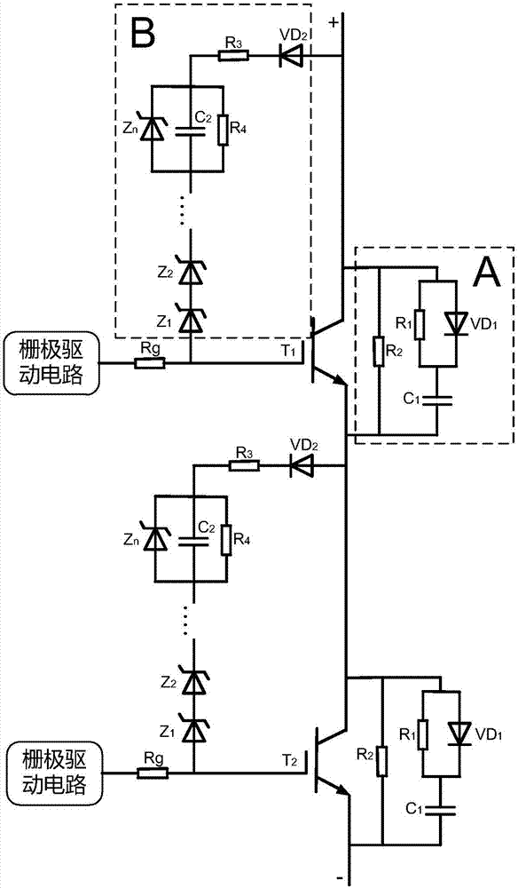
[0022] Such as figure 1 As shown, the present invention includes at least two IGBTs connected in series, and each IGBT is connected to a voltage equalizing circuit;

[0023] Such as figure 1 As shown, the present invention includes a load balancing control circuit A and a gate clamping circuit B, the load balancing control circuit A is connected in parallel to the collector and emitter of each IGBT, and the gate clamping circuit B is connected in parallel to the collector of each IGBT and gate.

[0024] Such as figure 1 As shown, the load balancing control circuit A is composed of capacitor C1, diode VD1, and resistors R1 and R2. The diode VD1 and resistor R1 are connected in parallel to the emitter of the IGBT through capacitor C1, and the resistor R2 is connected in parallel to the collector and emitter of the IGBT. .

[0025] Such as figure 1 A...


PUM


Abstract

The invention discloses an IGBT serial-connected composite voltage balancing circuit with grid-side and load-side control. The composite voltage balancing circuit comprises load-side and grid-side control voltage sharing circuits; the load-side voltage sharing circuit is connected in parallel between collectors and emitters of IGBTs, is composed of a resistor, a diode and a capacitor, and realizes static and dynamic voltage balancing in the load side; and the grid clamping voltage sharing circuit is connected in parallel between collectors and grids of IGBTs, is composed of a diode, a capacitor and a resistor, and can realize dynamic voltage balancing of the grids. The composite voltage balancing circuit realizes composite voltage balancing in the load side and the grid side via discrete passive devices, solves the problem of voltage imbalance due to characteristic difference of the devices and asynchronous driving signals in the IGBT switching on/off process, and ensures the working stability of the IGBT serial-connected circuit.

Description

technical field [0001] The invention belongs to the field of power electronics, in particular to an IGBT series composite voltage equalizing circuit controlled by a gate side and a load side. Background technique [0002] Insulated gate bipolar transistor (IGBT) devices have the advantages of high withstand voltage, fast switching speed, and easy driving, and are widely used in the field of pulse power. At present, the withstand voltage level (up to about 6.5kV) and capacity of a single IGBT device cannot meet the needs of high-voltage and high-power switches. The application of IGBT series technology is an effective method to improve the voltage level and power of semiconductor solid-state switches. Through the high voltage of each series-connected IGBT, the solid-state switch can achieve the purpose of high voltage resistance. [0003] The difficulty of the IGBT series technology is that due to the lack of strict synchronization of the IGBT drive signal, the performance d...

Claims


Application Information

Patent Timeline
Patent Type & Authority Applications(China)
IPC IPC(8): H03K17/081
CPCH03K17/08116H03K17/08112H03K2217/0054
Inventor 王剑平陈小天俞永华
Owner ZHEJIANG UNIV
Why Eureka
Try Eureka