Post-treatment package of engine exhaust and application

An exhaust post-treatment and engine technology, applied in exhaust treatment, exhaust devices, engine components, etc., to achieve large heat transfer area, improve anti-crystallization ability, and facilitate evaporation and pyrolysis

Inactive Publication Date: 2017-10-17
TENNECO SUZHOU EMISSION SYST
View PDF7 Cites 6 Cited by
  • Summary
  • Abstract
  • Description
  • Claims
  • Application Information

AI Technical Summary

Problems solved by technology

On the other hand, in order to ensure that the perforated plate 1' has sufficient mechanical strength, the material part between the perforated holes 2' is unavoidable

Method used


Image

  • Post-treatment package of engine exhaust and application
  • Post-treatment package of engine exhaust and application
  • Post-treatment package of engine exhaust and application

Examples


Embodiment Construction

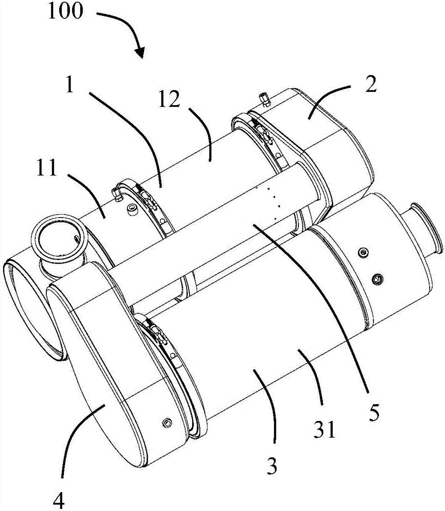
[0027] Please refer to Figure 3 to Figure 11 As shown, the present invention discloses an engine exhaust aftertreatment package 100 for use in an aftertreatment system such as an SCR to treat engine exhaust. In the illustrated embodiment of the present invention, the engine exhaust aftertreatment package 100 includes a first aftertreatment component 1, a first mixing chamber component 2 communicating with the first aftertreatment component 1, a first mixing chamber component 2 connected with the first The second after-treatment assembly 3 arranged side by side in the after-treatment assembly 1 , the second mixing chamber assembly 4 communicating with the second after-treatment assembly 3 , and the mixing tube communicating with the first and second mixing chamber assemblies 2 and 4 5. The first post-processing component 1 and the second post-processing component 3 are connected in series through the first and second mixing chamber components 2 , 4 and the mixing tube 5 .

...


PUM


Abstract

Disclosed is a post-treatment package of engine exhaust. The post-treatment package comprises a first post-treatment assembly, a first mixing cavity assembly and a mixing pipe communicated with the first mixing cavity assembly, wherein the mixing pipe comprises a swirling flow pipe which is at least partially located in the first mixing cavity assembly. The swirling flow pipe comprises a hollow inner cavity and a plurality of fins distributed around the periphery of the inner cavity in the circumferential direction. The first mixing cavity assembly comprises an installation base for installing a urea nozzle, and the urea nozzle is used for spraying atomized urea droplets into the mixing pipe. The post-treatment package of the engine exhaust further comprises a fine fiber element located in the mixing pipe, the fine fiber element is used for the exhaust and the urea droplets to pass through to further improve crushing and evaporation of the urea droplets. In this way, the post-treatment package of the engine exhaust has a high crystallization resistance capability. The invention further relates to application of the fine fiber element in the post-treatment package of the engine exhaust.

Description

technical field [0001] The invention relates to an engine exhaust after-treatment package and its application, and belongs to the technical field of engine exhaust after-treatment. Background technique [0002] At present, the metal structure of the mixer is used in the industry to achieve the mixing of urea droplets and exhaust gas. Usually, structures such as perforated plates and fins are set in the mixer to allow the urea droplets to collide with the metal-structured mixer so that the urea droplets are broken into smaller droplets to facilitate evaporation and pyrolysis on the metal surface . The status quo is due to the upgrade of emission regulations, which makes the current urea injection strategy more aggressive, such as starting a larger amount of urea injection at lower temperature and smaller exhaust flow. There is a heat conservation relationship here, one is the heat required for the evaporation and pyrolysis of urea droplets, and the other is the heat brought...

Claims


Application Information

Patent Timeline
Patent Type & Authority Applications(China)
IPC IPC(8): F01N3/20F01N3/28
CPCF01N3/2066F01N3/2892F01N2610/02F01N2610/1486
Inventor 李军良王天宇
Owner TENNECO SUZHOU EMISSION SYST
Why Eureka
Try Eureka