Binocular vision system-based image defogging method and device

A binocular vision system and parallax image technology, applied in the field of image processing, can solve problems such as increased noise interference, and achieve the effect of wide application occasions and rich effective information

Inactive Publication Date: 2017-10-17
SHANDONG NORMAL UNIV
View PDF1 Cites 4 Cited by
  • Summary
  • Abstract
  • Description
  • Claims
  • Application Information

AI Technical Summary

Problems solved by technology

Of course, the noise interf

Method used


Image

  • Binocular vision system-based image defogging method and device
  • Binocular vision system-based image defogging method and device
  • Binocular vision system-based image defogging method and device

Examples


Embodiment Construction

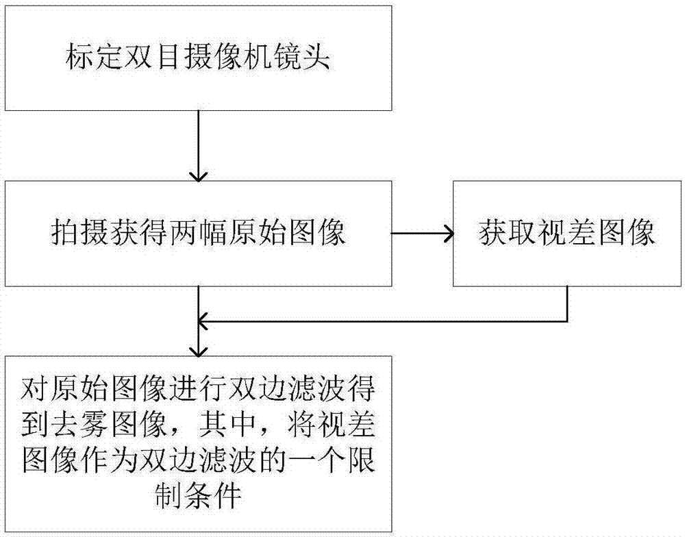
[0052] The present invention will be further described below in conjunction with the accompanying drawings and embodiments.

[0053] figure 1 It is a flow chart of the present invention to perform color image defogging.

[0054] This embodiment provides an image defogging method based on a binocular vision system, comprising the following steps:

[0055] Step 1: Calibrate the binocular camera lens;

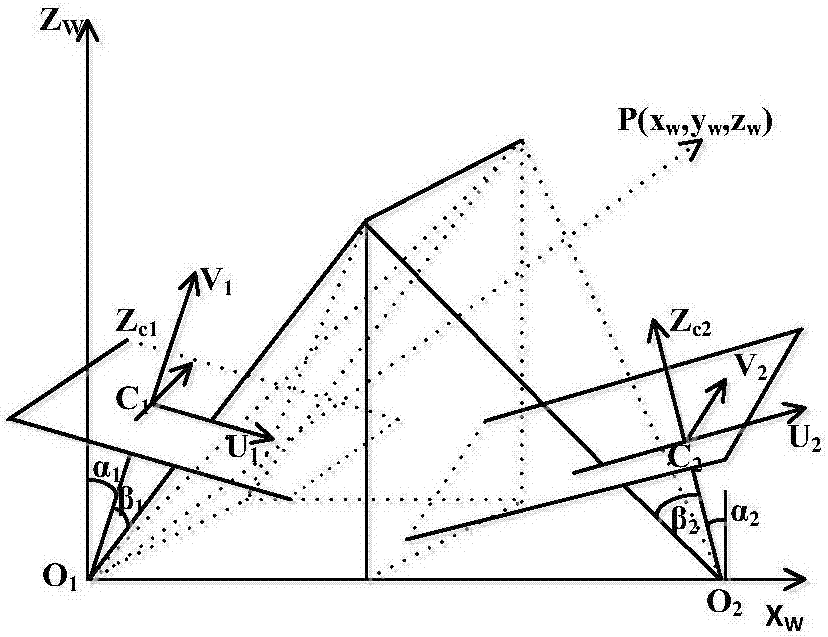
[0056] The structure of the binocular vision system is as follows: figure 2 shown. o 1 , O 2 are the focal points of two cameras with the same physical properties. with O 1 The coordinate system with the origin as the camera coordinate system. Focus on O 1 The system configuration will be explained using the camera on the left side of the camera as an example. Z c1 is the optical axis of the left viewpoint, which coincides with the coordinate axis of the camera, the optical axis is perpendicular to the image plane, and the coordinate system of the imaging plane (using ...


PUM


Abstract

The invention discloses a binocular vision system-based image defogging method. The method comprises the steps of calibrating the lens of a binocular camera, shooting and acquiring two original images by the binocular camera, acquiring a disparity image according to the two original images, and obtaining a defogged image through subjecting the two original images to bilateral filtering treatment. The disparity image is adopted as a limiting condition for the bilateral filtering treatment. According to the invention, the effective information of left image and right images is combined. Compared with the conventional defogging means based on a single image, resulted images are clearer and more abundant in effective information.

Description

technical field [0001] The invention relates to an image processing method, in particular to an image defogging method based on a binocular vision system. Background technique [0002] The binocular stereo vision algorithm is a new type of image information acquisition algorithm based on two viewpoints. Compared with the monocular vision algorithm, the amount of image information collected by it is more abundant, and the effective information about a certain pixel can reach up to Twice as much as before, and because of this, the target image obtained after the clearing algorithm is clearer than the monocular vision rendering. Of course, the noise interference is relatively doubled. [0003] At present, a technical problem urgently needed by those skilled in the art is: how to effectively denoise the target image acquired by the binocular stereo vision system, and extract more effective information. Contents of the invention [0004] In order to solve the above problems, ...

Claims


Application Information

Patent Timeline
IPC IPC(8): G06T7/33G06T7/80G06T7/38G06T7/50
CPCG06T2207/20028
Inventor 杨峰张化祥张田张东香
Owner SHANDONG NORMAL UNIV
Why Eureka
Try Eureka