Jet cooler

A technology of jet cooling and jet tube, which is applied in the petroleum industry, recovery of liquid hydrocarbon mixtures, etc., can solve the problems of vertical installation of spray cooling tower or cooling sieve plate tower, large footprint, easy condensation in the cooling tower, cooling liquid flow rate, etc. Slow down and other problems, to achieve the effect of excellent work performance, small installation area, and rapid cooling

Inactive Publication Date: 2010-05-12
SHANDONG UNIV OF TECH
View PDF0 Cites 1 Cited by
  • Summary
  • Abstract
  • Description
  • Claims
  • Application Information

AI Technical Summary

Problems solved by technology

[0003] At present, in the field of biomass pyrolysis and liquefaction technology, research institutions that use pyrolysis gas and low-temperature bio-oil direct mixing heat exchange technology generally use spray cooling towers or cooling sieve plate towers. For example, in biomass pyrolysis Relevant research institutions such as University of Science and Technology of China, Shandong University of Technology and Northeast Forestry University, which have achieved outstanding results in liquefaction technology, all adopt this method. The disadvantage is that the vertical installation of spray cooling tower or cooling sieve plate tower occupies a large area and the cooling flow Large, due to the slow flow rate of the cooling liquid in the tower, the charcoal ash carried in the pyrolysis gas is easy to condense in the cooling tower, and the tar produced during the cooling process of the pyrolysis gas is bonded to the charcoal ash, which is not easy to remove
The thermal cracking demonstration plant with a biomass feed rate of 200kg / h established by the Spanish Union Fenosa Power Company in 1993 and the 200kg / h feed rate developed by the Biomass Technology Group (BTG) of the University of Twente in the Netherlands in 2000 The improved rotating cone reactor pyrolysis liquefaction process uses a shell-and-tube heat exchange cooler as the cooling technology. The defect is that during the cooling process of the pyrolysis gas, the charcoal ash carried in the pyrolysis gas and The tar produced by the cooling of the pyrolysis gas condenses, and the pipeline is quickly blocked

Method used


Image

  • Jet cooler
  • Jet cooler
  • Jet cooler

Examples


Embodiment Construction

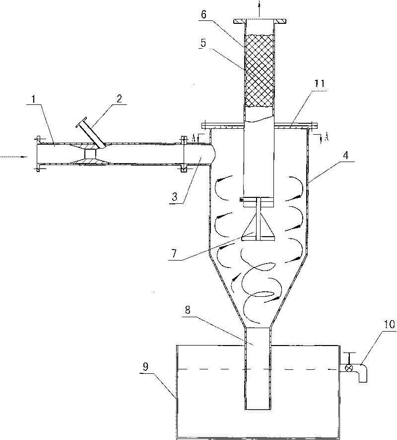
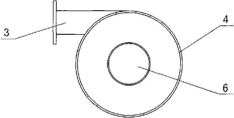
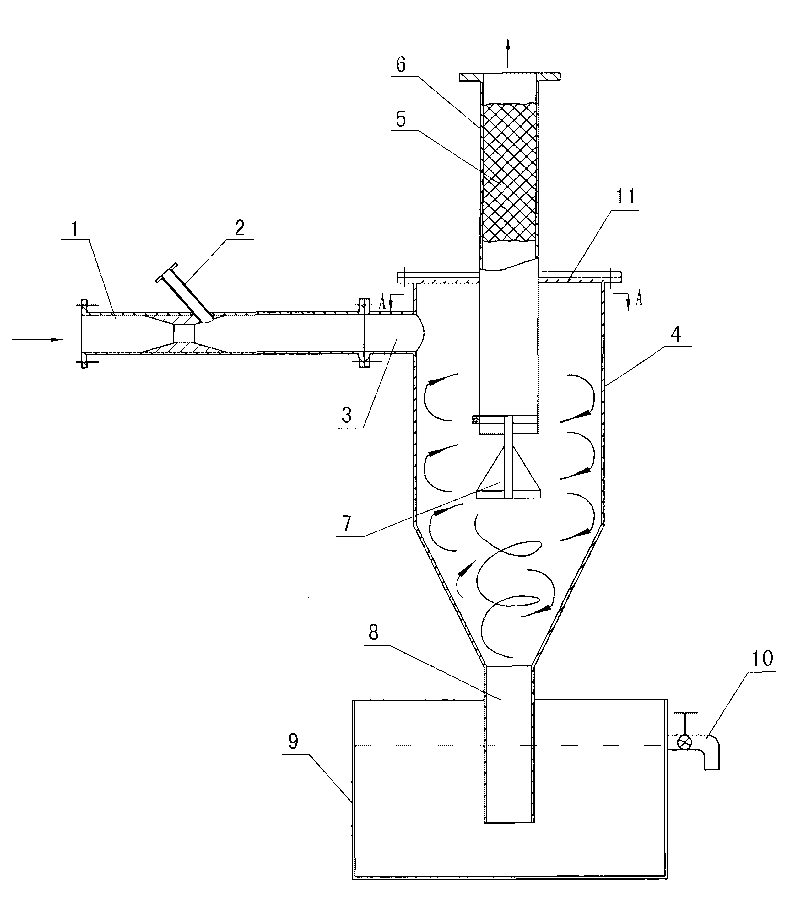
[0016] The stacked wire mesh 5 is arranged in the air outlet pipe 6 of the cyclone separator 4 to form a demisting device. An air flow blocking cone 7 is hoisted at the bottom of the air outlet pipe 6. The air flow blocking cone 7 is in the shape of a cone, with the cone end facing upwards, and the air flow blocking cone 7 is in the shape of a cone. The axis of the trachea 6 is aligned. The mixed flow inlet 3 of the cyclone separator 4 is a horizontal tangential inlet, the input end is connected to the Venturi jet tube 1, and the pyrolysis gas inlet 2 is arranged at the diffusion section of the Venturi jet tube 1, and is 45 to the axis of the Venturi jet tube 1. degree angle, the liquid outlet 8 at the bottom of the cyclone separator 4 is inserted into the liquid in the oil storage tank 9 . In this way, the high-speed fluid carrying the pyrolysis gas enters the cyclone separator 4 horizontally and tangentially to rotate, mix and exchange heat, and then realize rapid heat excha...


PUM


Abstract

The invention provides a jet cooler which comprises a venturi jet pipe and a cyclone separator. The jet cooler is characterized in that a mixed flow inlet of the cyclone separator is connected with the venturi jet pipe, a thermolysis air inlet is arranged at a dispersion section of the venturi jet pipe and forms an included angle of 30-50 degrees with the axis of the venturi jet pipe, and a silk screen, an airflow obstruction cone cylinder and an oil storage tank are additionally arranged, wherein the stacked silk screen is arranged in an air outlet pipe of the cyclone separator, the bottom of the air outlet pipe is hung with the airflow obstruction cone cylinder, and a liquid flow outlet at the bottom of the cyclone separator is inserted into the liquid of the oil storage tank. Cold biologic oil ejected by the venturi jet pipe is mixed with thermolysis air to form high-speed fluid carrying the thermolysis air, and the high-speed fluid enters the cyclone separator horizontally from the mixed flow inlet of the cyclone separator in a tangential direction for carrying out rotary mixed heat exchange so as to realize the quick heat exchange, cooling and liquefaction of liquefiable gas. Because the cold biologic oil has high flow rate and is directly mixed and contacts with the thermolysis air, the heat exchange area is large, the heat exchange effect is good, the occupied area in installation is small, the structure is simplified, and the working performance is superior.

Description

technical field [0001] The invention provides a jet cooler, which belongs to the technical field of chemical cooling equipment. Background technique [0002] One of the cooling methods used in the biomass flash pyrolysis liquefaction process is to directly mix low-temperature bio-oil and high-temperature pyrolysis gas to cool and shock the pyrolysis gas, so as to condense the condensable gas in the pyrolysis gas to obtain bio-oil. The bio-oil flows into the oil storage tank, and other non-liquefiable gases are discharged from the condensing unit. This process requires that the high-temperature pyrolysis gas and low-temperature bio-oil entering the condensing unit are directly mixed for heat exchange. The high-temperature pyrolysis gas is quickly cooled to below 60°C, and the liquefiable gas in the pyrolysis gas becomes liquid and flows into the oil storage tank. Other non-liquefiable gases are sucked out of the condensing device by the induced draft fan. [0003] At presen...

Claims


Application Information

Patent Timeline
Patent Type & Authority Applications(China)
IPC IPC(8): C10G5/06
Inventor 李永军柏雪源易维明李志合
Owner SHANDONG UNIV OF TECH
Why Eureka
Try Eureka