Laminar flow condenser for thermal decomposition and liquidation of biomass

A technology of biomass pyrolysis and condenser, which is applied in the preparation of biofuels, liquid hydrocarbon mixtures, and special forms of dry distillation, etc. It can solve the problems of easy condensation in cooling towers, tar and charcoal ash bonding, and large cooling liquid flow. problems, to achieve the effect of easy cleaning, high heat exchange efficiency and large temperature gradient

Active Publication Date: 2011-10-12
SHANDONG UNIV OF TECH
View PDF7 Cites 0 Cited by
  • Summary
  • Abstract
  • Description
  • Claims
  • Application Information

AI Technical Summary

Problems solved by technology

[0003] At present, in the field of biomass pyrolysis and liquefaction technology, research institutions that use pyrolysis gas and low-temperature bio-oil direct mixing heat exchange technology generally use spray cooling towers or cooling sieve plate towers, such as in biomass pyrolysis Relevant research institutions such as University of Science and Technology of China, Shandong University of Technology and Northeast Forestry University, which have achieved outstanding results in liquefaction technology, all adopt this method. The liquid flow rate is large, the charcoal ash carried in the pyrolysis gas is easy to condense in the cooling tower, and the tar produced during the cooling process of the pyrolysis gas is bonded to the charcoal ash, which is not easy to remove
The thermal cracking demonstration plant with a biomass feed rate of 200kg / h established by the Spanish Union Fenosa Power Company in 1993 and the 200kg / h feed rate developed by the Biomass Technology Group (BTG) of the University of Twente in the Netherlands in 2000 The improved rotating cone reactor pyrolysis liquefaction process uses a shell-and-tube heat exchange cooler as the cooling technology. The defect is that during the cooling process of the pyrolysis gas, the charcoal ash carried in the pyrolysis gas and The tar produced by the cooling of the pyrolysis gas condenses, and the pipeline is quickly blocked

Method used


Image

  • Laminar flow condenser for thermal decomposition and liquidation of biomass
  • Laminar flow condenser for thermal decomposition and liquidation of biomass
  • Laminar flow condenser for thermal decomposition and liquidation of biomass

Examples


Embodiment Construction

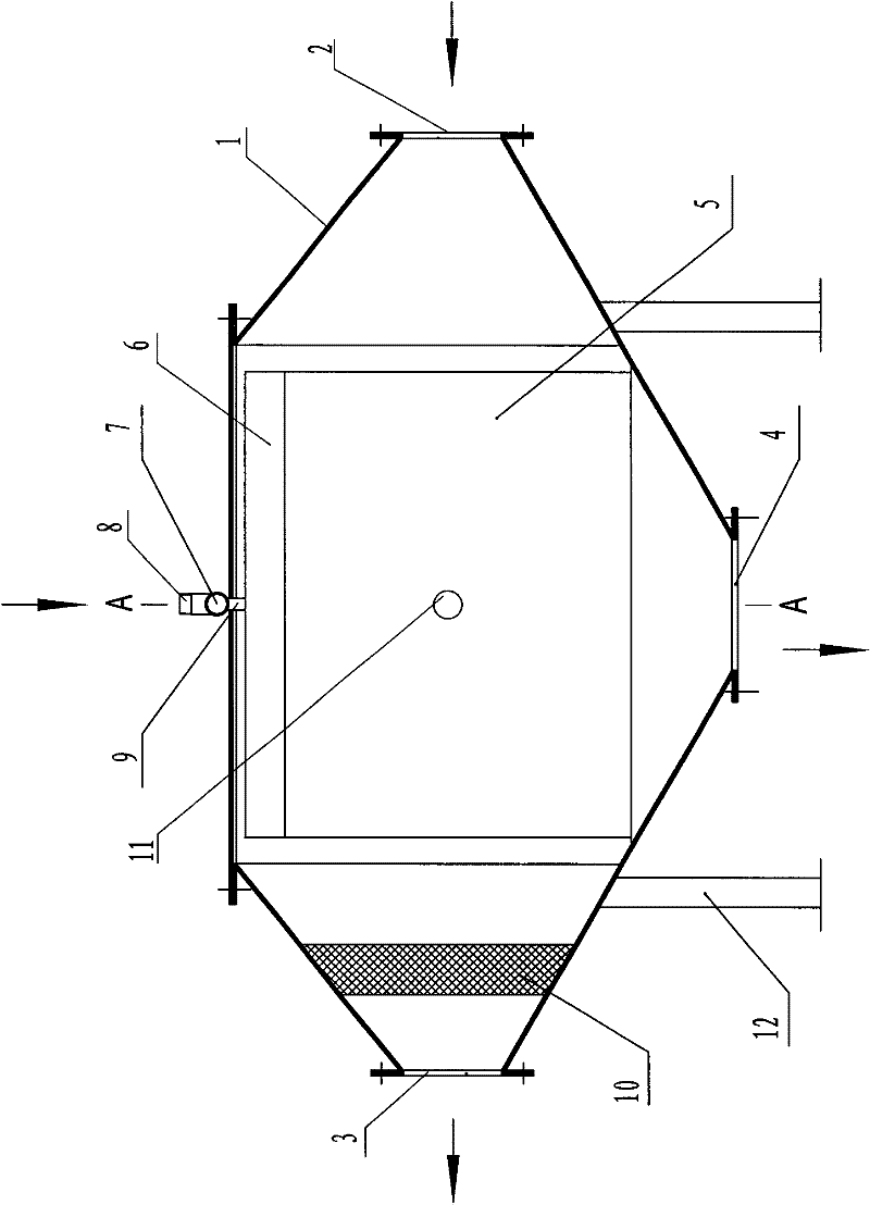
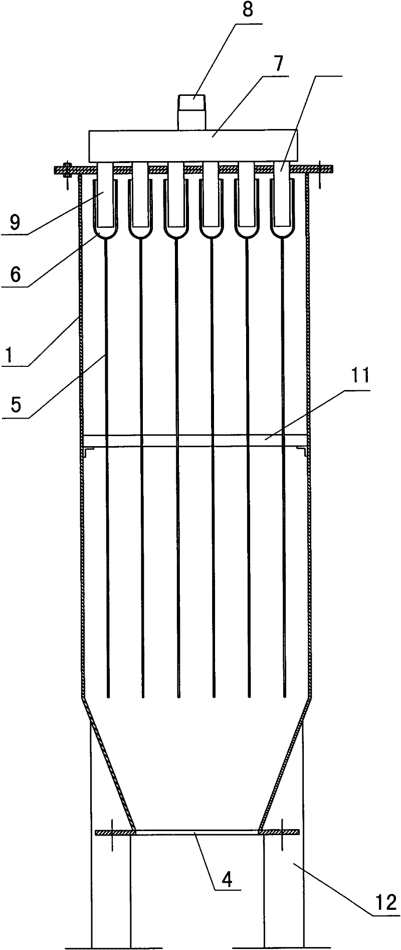
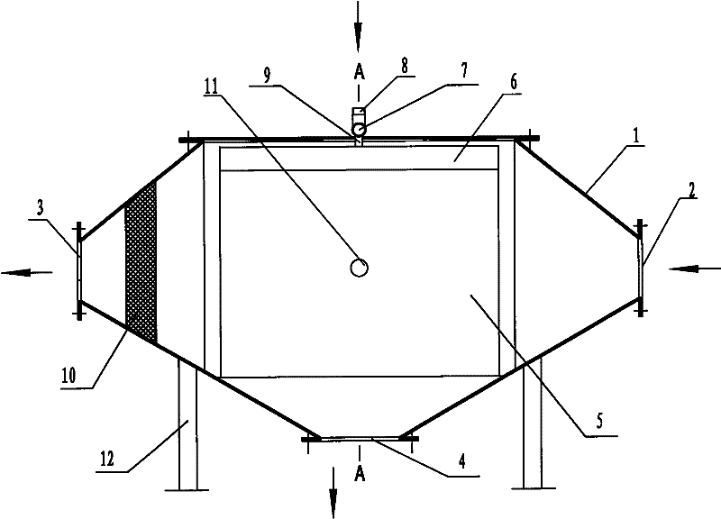
[0017] exist Figure 1-2 In the shown embodiment: the cylinder body 1 is installed horizontally on the support 12, the cross section of the cylinder body 1 is rectangular, one end is the pyrolysis gas inlet 2, and the other end is the pyrolysis gas outlet 3, the top of the cylinder body 1 is provided with A bio-oil inlet 8 and a bio-oil outlet 4 are provided at the bottom. A plurality of condensing plates 5 parallel to each other and equally spaced are arranged in the barrel 1 along the flow direction of the pyrolysis gas. The beam 11 passes through each condensing plate 5 horizontally in turn, and It is fixedly connected with each condensing plate 5, and the condensing plate 5 is fixedly installed in the cylinder body 1. An overflow groove 6 is provided on the top of each condensing plate 5. The overflow groove 6 is the same length as the condensing plate 5, and the overflow groove The bottom of 6 is fixedly installed on the top of the condensation plate 5, the side wall of t...


PUM


Abstract

The invention provides a laminar flow condenser for thermal decomposition and liquidation of biomass. The laminar flow condenser comprises a horizontal cylinder, wherein the cross section of the horizontal cylinder is rectangular; a pyrolytic gas inlet is arranged at one end of the cylinder, and a pyrolytic gas outlet is arranged at the other end of the cylinder; a biological oil inlet is arranged on the top of the cylinder; and a biological oil outlet is arranged at the bottom of the cylinder. The laminar flow condenser is characterized in that a plurality of condensing plates, which are parallel to each other, are arranged inside the cylinder along the pyrolytic gas flowing direction; an overflow tank is arranged on the top end of each condensing plate; side walls of the overflow tank are symmetrical relative to the condensing plate; a horizontal distributing pipe is arranged on the top end of the cylinder and is communicated with the biological oil inlet; the distributing pipe is provided with a branched pipe corresponding to each overflow tank; a bottom outlet of the branched pipe is inserted into the overflow tank; and a silk screen is arranged inside the cylinder at the pyrolytic gas outlet. According to the laminar flow condenser, hot gas is in laminar conditions and flows through a liquid flow membrane; due to the low flow velocity, the thin airflow layers and the large temperature gradient, the heat exchange efficiency is high; carbon ash and coke tar carried in the pyrolytic gas flow out from the condensing plates along with the liquid flow and are not easy to condense; the laminar flow condenser has the advantages of simple structure and convenience for disassembly and assembly; and the condensing plates are easy to clean and have excellent working performance.

Description

technical field [0001] The invention provides a laminar flow condenser for pyrolysis and liquefaction of biomass, which belongs to the technical field of renewable energy. Background technique [0002] One of the cooling methods used in the biomass flash pyrolysis liquefaction process is to directly mix low-temperature bio-oil and high-temperature pyrolysis gas to cool and shock the pyrolysis gas, so as to condense the condensable gas in the pyrolysis gas to obtain bio-oil. The bio-oil flows into the oil storage tank, and other non-liquefiable gases are discharged from the condensing unit. This process requires that the high-temperature pyrolysis gas and low-temperature bio-oil entering the condensing device are directly mixed for heat exchange, the high-temperature pyrolysis gas is quickly cooled to below 60°C, and the liquefiable gas in the pyrolysis gas becomes liquid and flows into the oil storage tank. The non-liquefiable gas is sucked out of the condensing unit by the...

Claims


Application Information

Patent Timeline
IPC IPC(8): C10B53/02C10B57/00C10G1/00
CPCY02E50/10
Inventor 李永军易维明李志合柏雪源
Owner SHANDONG UNIV OF TECH
Why Eureka
Try Eureka