Air compressor oil and gas filter structure and screw air compressor with the filter structure

A technology of air compressor and filter structure, applied in machine/engine, mechanical equipment, liquid fuel engine, etc., can solve the problems of leakage, shorten the service life, and easily form oil mist, so as to reduce the probability of leakage and reduce the installation process. , reduce the effect of pipe joints

Active Publication Date: 2020-06-19
宁波天风汽车科技有限公司
View PDF9 Cites 0 Cited by
  • Summary
  • Abstract
  • Description
  • Claims
  • Application Information

AI Technical Summary

Problems solved by technology

[0005] The existing air compressors have the following deficiencies: firstly, the connecting pipelines are basically exposed, resulting in many pipe joints, many installation links, and there is also a risk of leakage; secondly, in the cold weather in the north, the air compressor needs to be The oil and gas tank is heated to make the oil passage unobstructed; again, the compressed air from the oil and gas tank has a high oil content, which makes the filter load of the oil and gas separator heavier, reducing its service life and requiring frequent replacement; finally, the oil and gas Oil mist is easy to form in the tank, which affects the subsequent oil and gas separation

Method used


Image

  • Air compressor oil and gas filter structure and screw air compressor with the filter structure
  • Air compressor oil and gas filter structure and screw air compressor with the filter structure
  • Air compressor oil and gas filter structure and screw air compressor with the filter structure

Examples


Embodiment Construction

[0030] The present invention will be further described in detail below in conjunction with the accompanying drawings and embodiments.

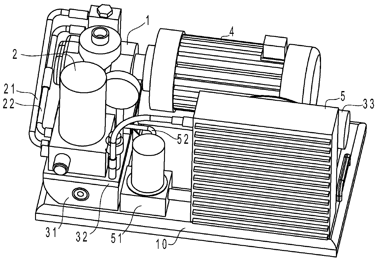
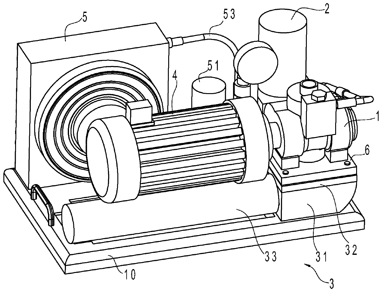
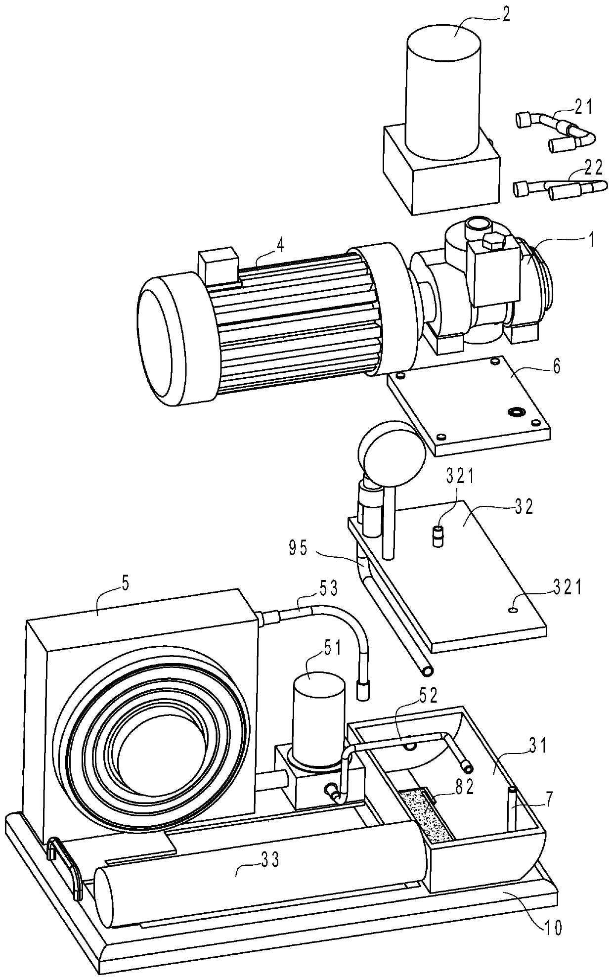
[0031] like Figure 1 to Figure 5 As shown, the air compressor in this embodiment includes a base plate 10 , a screw air compressor host 1 , an oil and gas tank 3 , an oil and gas separator 2 , a motor 4 , an oil filter 51 and a cooler 5 . The oil and gas tank 3 , the cooler 5 and the oil filter 51 are arranged on the bottom plate 10 .

[0032] The power output end of the motor 4 is connected with the power input end of the screw air compressor host 1, the oil inlet end of the cooler 5 is connected with the oil outlet end of the oil gas tank 3 through the first oil pipe, and the oil outlet end of the cooler 5 is connected with the screw air outlet. The oil inlet end of the compressor host 1 is connected through a second oil pipe 52 . The air outlet end of the screw air compressor host 1 is connected to the oil and gas tank 3 through the exha...


PUM


Abstract

Disclosed is an oil-air filtering structure of an air compressor. The oil-air filtering structure of the air compressor comprises a screw-type air compressor main machine, an oil-air tank and an oil-air separator. The air outlet end of the screw-type air compressor main machine is connected into the oil-air tank through an air exhausting pipe. The oil-air filtering structure of the air compressor is characterized in that the oil-air tank comprises a tank body, a cover plate and a drum body, the upper end of the tank body is provided with an installing end opening, the side wall of the tank body is provided with a first communicating hole and a second communicating hole, the air exhausting pipe is located in the oil-air tank and close to the bottom of the oil-air tank, one end of the air exhausting pipe communicates with a first through hole of the cover plate, the other end of the air exhausting pipe penetrates through the second communicating hole of the tank body and extends into the drum body, a first filtering material is arranged on the position, close to the first communicating hole, of the inner side of the drum body, a second filtering material is arranged on the position, close to the first communicating hole, of the tank body, and a third filtering material is arranged on the position, close to the second through hole, of the inner side of the cover plate. The invention further discloses the air compressor. According to the oil-air filtering structure of the air compressor, the air exhausting pipe is arranged at the bottom of the oil-air tank and can be used for heating, the number of pipe joints is reduced, the leakage probability is reduced, and then the filtering materials can remove oil mist.

Description

technical field [0001] The invention relates to an air compressor. Background technique [0002] Air compressors are generally installed on large vehicles, which can provide compressed air sources for vehicle braking, door opening and closing, etc. At present, the common screw air compressors are mainly used, and the volume can be made as small as possible. [0003] A common screw air compressor includes a motor, a main engine, an oil and gas tank, a cooler, a filter and an oil and gas separator, and the main engine adopts twin-screw compression. Working principle: The motor works, drives the main engine to start, the air enters the main engine from the intake valve, enters the oil and gas tank from the air outlet of the main engine, the oil in the oil and gas tank is pressed onto the cooler, the cooled oil passes through the filter, and then enters the main engine. At the same time, the air enters the oil-air separator from the outlet of the oil-air tank, and then the sepa...

Claims


Application Information

Patent Timeline
Patent Type & Authority Patents(China)
IPC IPC(8): F04C29/02F04C29/04F04C29/12F04C23/02
CPCF04C23/02F04C29/026F04C29/028F04C29/04F04C29/12
Inventor 陆亚明
Owner 宁波天风汽车科技有限公司
Why Eureka
Try Eureka