
High-voltage electric appliance fiber gating temperature measuring system

A technology of optical fiber gratings and high-voltage electrical appliances, which is applied in the field of temperature monitoring equipment, can solve problems such as the inability to realize the temperature measurement of the switch cabinet knife switch connection points and contacts, the limit of the safe operation level of the power system, and the unusable sensors, etc., to reduce the number and The effect of workload, reliable power guarantee, and easy installation

Inactive Publication Date: 2017-10-20
北京昕天卫光电科技有限公司
View PDF5 Cites 0 Cited by
  • Summary
  • Abstract
  • Description
  • Claims
  • Application Information

AI Technical Summary

Problems solved by technology

[0003] Over the years, due to the limitation of technical level, the level of safe operation of the power system has been limited. Although infrared thermometers, infrared imagers, temperature-sensing cables, and traditional point-type temperature measurement systems have been used to solve the above problems, they have not been able to realize the switch The temperature measurement of circuit breakers, knife switch joints and contacts in the cabinet is powerless for fully enclosed armored cabinets
[0004] Most of the equipment in the power industry is in a strong electromagnetic field, and general electrical sensors cannot be used

Method used


Image

  • High-voltage electric appliance fiber gating temperature measuring system
  • High-voltage electric appliance fiber gating temperature measuring system
  • High-voltage electric appliance fiber gating temperature measuring system

Examples


Embodiment Construction

[0022] In order to make the object, technical solution and advantages of the present invention clearer, the present invention will be further described in detail below in conjunction with the accompanying drawings and specific embodiments.

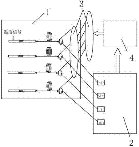
[0023] figure 1 The fiber grating temperature sensor of the present invention is shown to illustrate the working principle of the system; the present invention is developed based on the principle of optical fiber grating photosensitivity, and the temperature detection optical cable 1 is distributed at the measurement point, and the temperature signal at this point is collected; the external temperature The changed temperature signal is transmitted to the fiber grating temperature detector, which causes the drift of the center wavelength of the laser through the fiber grating. According to the experimental research, the drift of the laser center wavelength is linear with the temperature change; the signal demodulation analysis of the back-en...


PUM

PropertyMeasurementUnit
heightaaaaaaaaaa
diameteraaaaaaaaaa
thicknessaaaaaaaaaa

Abstract

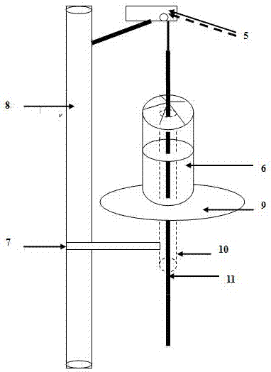
The invention provides a high-voltage electric appliance fiber grating temperature measuring system, including a fiber grating sensor and an anti-creepage protection cover. The fiber grating sensor (1) is pasted with aviation glue in the vicinity of a contact needing detection, and a stainless steel buckle with an insulating layer is utilized to reinforce installation; the anti-creepage protection cover includes an isolation column (6) and a pedestal (9), and the external diameter of the pedestal (9) is larger than that of the isolation column (6), the middle of the isolation column (6) is provided with a sleeve (10), thereby providing effective protection and isolation for the fiber grating sensor (1). The temperature measuring system has the advantages of intrinsic safety, electromagnetic interference resistance, small and exquisite volume, easy installation and the like, is suitable for monitoring of temperature of various hotspots in high-voltage large-current environment in an electric power system, and can guarantee safe operation of electric power facilities and equipment; and at the same time, the high-voltage electric appliance fiber grating temperature measuring system has an intelligent analysis function, accurately measures temperature, is safe and adopts power-free detection, reduces the number and workload of maintenance personnel, and provides a safe and reliable power guarantee.

Description

technical field [0001] The invention relates to temperature monitoring equipment of electric power equipment, in particular to an optical fiber grating power temperature measurement system developed based on the principle that the temperature change is proportional to the wavelength change of optical fiber refraction. Background technique [0002] At present, my country's power system, all power substations, substations, etc., have potential safety hazards of temperature rise. The current traditional temperature measurement method uses manual temperature measurement (the labor cost is relatively high), which cannot be measured in real time, and the time interval is relatively long. The hidden danger is relatively large. Using robots to measure temperature, there are also hidden dangers that cannot be measured in real time, and the maintenance cost of robots is generally unacceptable. Wireless online real-time temperature measurement, there is magnetic field interference, and ...

Claims


Application Information

Patent Timeline
Patent Type & Authority Applications(China)
IPC IPC(8): G01K11/32G01K11/3206
CPCG01K11/32
Inventor 罗时高
Owner 北京昕天卫光电科技有限公司
Learn More