
Lateral load action-considered longitudinal multi-span instability load-end shrink curve determination method.

A side load and determination method technology, applied in special data processing applications, instruments, electrical digital data processing, etc., can solve the problems of large modeling and calculation time, high requirements, etc., to achieve ship design safety, improve efficiency and accuracy, Effects that improve accuracy and speed

Active Publication Date: 2017-10-20
708TH RES INST OF CSSC
View PDF3 Cites 4 Cited by
  • Summary
  • Abstract
  • Description
  • Claims
  • Application Information

AI Technical Summary

Problems solved by technology

However, the requirements for computer hardware and software operators are relatively high, and it takes a lot of modeling and calculation time

Method used


Image

  • Lateral load action-considered longitudinal multi-span instability load-end shrink curve determination method.
  • Lateral load action-considered longitudinal multi-span instability load-end shrink curve determination method.
  • Lateral load action-considered longitudinal multi-span instability load-end shrink curve determination method.

Examples


Embodiment Construction

[0055] The present invention will be further described below in conjunction with the accompanying drawings and embodiments.

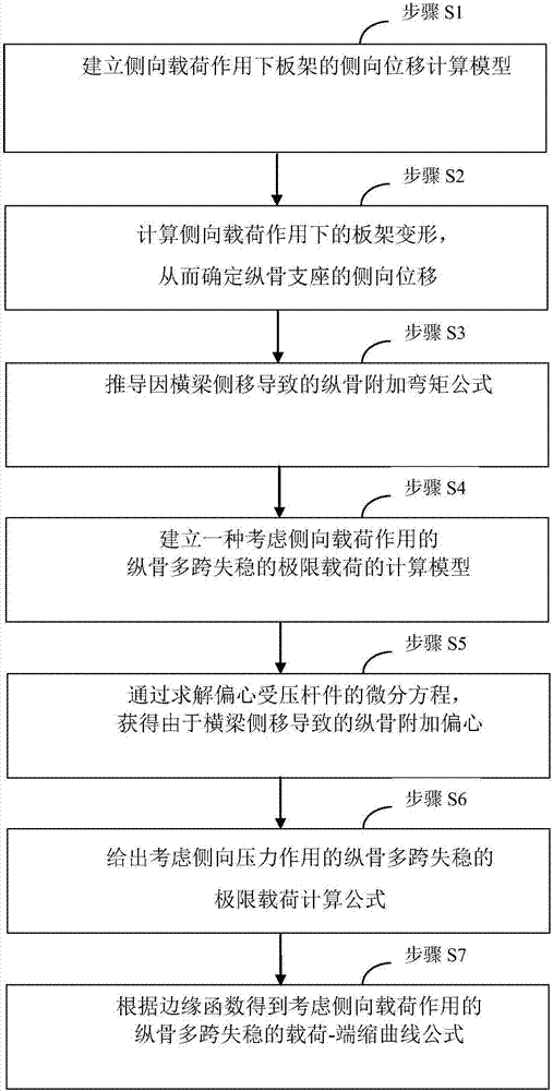
[0056] In a preferred embodiment, as figure 1 As shown, a method for determining the load-contraction curve of longitudinal multi-span instability considering the lateral load.

[0057] Methods of determination may include:

[0058] Step S1, establishing a calculation model for the lateral displacement of the plate frame under the action of the lateral load;

[0059] Step S2, using the beam as the elastic support of the longitudinal frame, according to the simple frame theory of "Ship Structural Mechanics", calculate the deformation of the frame under the action of lateral load, so as to determine the lateral displacement of the longitudinal frame support;

[0060] Step S2, deriving the formula for the additional bending moment of the longitudinal bone caused by the lateral movement of the beam;

[0061] Step S3, introduce the overall deformation of ...


PUM


Abstract

The invention relates to the field of ship structure design, and discloses a lateral load action-considered longitudinal multi-span unstable load-end shrink curve determination method. The method comprises the following steps of: establishing a theoretical model which considers the influences of lateral migration, of a crossbeam or ribbed plate (hereinafter uniformly referred to as crossbeam), caused by overall deformation of a grillage, and longitudinal multi-span instability due to actions of bearing longitudinal axial force and lateral pressure; obtaining longitudinal additional eccentricity caused by lateral migration of the crossbeam through solving a differential equation; giving an extreme load calculation formula which considers longitudinal multi-span instability caused by lateral load action; and obtaining a longitudinal multi-span instability load-end shrink curve formula which considers the lateral load action through an edge function and plastically-corrected extreme load of longitudinal multi-span instability. The method can be used for expanding the existing Smith method for ship beam extreme load calculation, determining the double-bottom effect of ship beam extreme load and improving the precision and speed of ship beam ultimate bending moment calculation.

Description

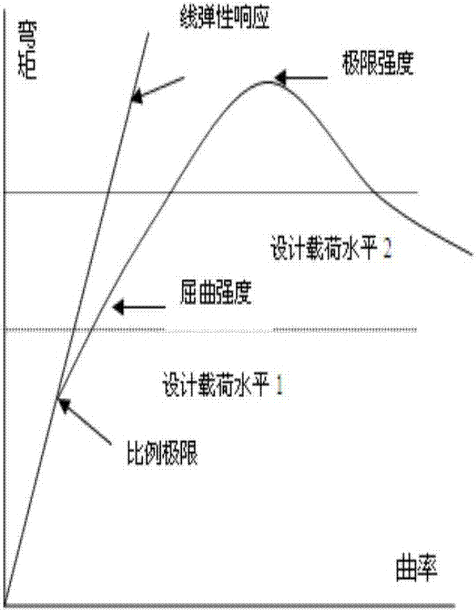
technical field [0001] The invention relates to the field of ship structure design, in particular to a method for determining a load-contraction curve for multi-span instability of longitudinals in consideration of lateral loads. Background technique [0002] The hull girder ultimate load is the maximum ability of the hull structure to resist overall collapse, and it is the extreme value of the vertical bending moment-curvature curve of the hull cross section, such as figure 1 shown. The determination and evaluation of hull girder ultimate load is of great significance to ensure ship safety and design rationality, and it is a recent research hotspot in international ship structural mechanics. Since 2006, the International Association of Classification Societies (IACS) has clearly stipulated in the International Common Structural Rules (CSR) for bulk carriers and oil tankers that ship design must carry out hull girder limit load evaluation . The CSR code stipulates that th...

Claims


Application Information

Patent Timeline
IPC IPC(8): G06F17/50
CPCG06F30/15G06F30/20
Inventor 万琪王福花吴剑国彭营豪朱汉波
Owner 708TH RES INST OF CSSC
Learn More