Display device, source electrode drive circuit, and control circuit for source electrode drive circuit

A source drive and circuit technology, applied to static indicators, instruments, etc., can solve the problem of deteriorating the noise performance of source drive circuits, and achieve the effect of reducing overshoot voltage and overshoot effect

Pending Publication Date: 2017-10-20
CHIPONE TECH BEIJINGCO LTD
View PDF8 Cites 7 Cited by
  • Summary
  • Abstract
  • Description
  • Claims
  • Application Information

AI Technical Summary

Problems solved by technology

At time t1, the switch signal open and the output control signal outen jump from low level to high level, the operational amplifier is turned on, the transistor T1 is turned on, and the data channel where the operational amplifier and transistor T1 are located is turned on, but since the operational amplifier is turned on again , it will cause an overshoot effect on the output load, such as figure 2 As shown, for a period of time starting from time t1, the source drive signal out output by the source drive circuit generates a large overshoot voltage, and two points A, B, A, B, which are 2.876 μs apart on the time axis are selected The voltage difference between the two points is 793.1mV. It can be seen that when the voltage of the source drive signal out is 4.8V, the overshoot voltage generated is 793.1mV. This is caused by the mismatch of the instantaneous charge and discharge current, which will deteriorate the source Noise Performance of Pole Drive Circuit

Method used


Image

  • Display device, source electrode drive circuit, and control circuit for source electrode drive circuit
  • Display device, source electrode drive circuit, and control circuit for source electrode drive circuit
  • Display device, source electrode drive circuit, and control circuit for source electrode drive circuit

Examples


Embodiment Construction

[0026] The following disclosure provides many different implementations, or examples, for implementing different features of the application. Specific examples of components or arrangements are described below to simplify the present disclosure. Of course, these are merely examples and are not intended to limit the invention.

[0027] Furthermore, in the description and claims, the terms "first", "second", etc. are used to distinguish between similar elements, and do not necessarily describe a temporal order, spatial order, hierarchical order, or any other order, should It is to be understood that the terms so used are interchangeable under appropriate circumstances and that the embodiments of the invention described herein are capable of operation in other sequences than described or illustrated herein.

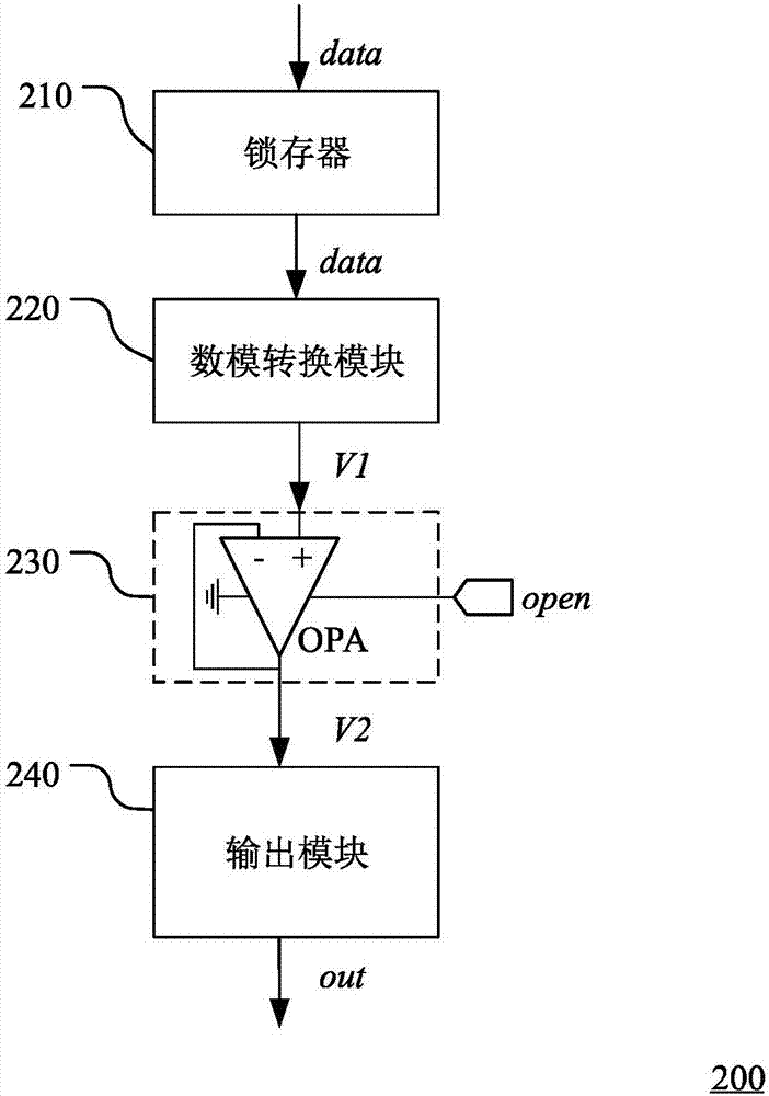
[0028] image 3 A schematic structural diagram of a source driving circuit in a display device according to an embodiment of the present invention is shown.

[0029] Such...


PUM


Abstract

The invention discloses a display device, a source electrode drive circuit, and a control circuit for the source electrode drive circuit. The source electrode drive circuit comprises a digital-analog conversion module which is used for converting a digital signal into an analog voltage; an amplification module which is used for amplifying the analog voltage under the control of a switching signal; and an output module which is connected between the amplification module and an output end, and is used for providing a source electrode drive signal for a pixel unit. The output module comprises a plurality of parallel control units, and the control units are sequentially connected according to a sequence from the big conduction resistance to the small conduction resistance. Compared with the prior art, the source electrode drive circuit can effectively reduce the overshoot effect of the circuit, and reduce the noise of the circuit.

Description

technical field [0001] The invention relates to the technical field of liquid crystal display, in particular to a display device, a source driving circuit and a control method thereof. Background technique [0002] In recent years, with the continuous advancement of display technology, liquid crystal displays have become the most common display devices on the market. For a general liquid crystal display, the liquid crystal driving circuit includes a source driving circuit and a gate driving circuit. [0003] figure 1 A schematic structural diagram of a source driving circuit in a display device in the prior art is shown. In the figure, only the source driving circuits of multiple data channels D1-Dn are shown, and n is a non-zero natural number. The source drive circuit includes a shift register 110, a latch 120 corresponding to each data channel, a digital-to-analog converter 130, an output buffer 140, and an output module 150, wherein the output buffer 140 includes a A...

Claims


Application Information

Patent Timeline
Patent Type & Authority Applications(China)
IPC IPC(8): G09G3/36
CPCG09G3/3688G09G2330/021G09G2300/0828G09G2310/0286
Inventor 吴昭呈祝军
Owner CHIPONE TECH BEIJINGCO LTD
Why Eureka
Try Eureka